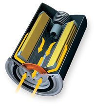
Oil Filter Flow Diagram
Pfds are used for visitor information and new employee training.
Oil filter flow diagram. The water for the oil cooler comes through an internal passage from the thermostat housing. Flowchart (or flow chart) is a type of diagram that describe processes. Data flow diagrams templates include lots of data flow diagram shapes, data process, center to center, multiply process, loop on center, line connector, state, start. Creating data flow diagram with free templates and examples.
The process flow diagram (pfd) is a critical component of process design. Oil come from platform separator two filters work & the other under back washing every 8 hrs. Schematic flow diagram of a typical oil refinery. An oil filter is a filter designed to remove contaminants from engine oil, transmission oil, lubricating oil, or hydraulic oil.
These diagrams compose of blocks, often rectangular, connected by arrows. Process flow diagram what is a pfd? Flow chart 101—all you need to know—definition, flowchart symbols, history, how to make a flowchart, examples & templates, tools & more. Full flow means all of the oil is filtered …every drop of it passes through the engine oil filter before it is pumped throughout the engine.
- 2016 Volvo Truck Fuse Box Diagram
- 2005 Ram 1500 Belt Diagram
- 2002 Buick Century Radio Wiring Diagram
It is absolutely necessary that chemical engineers know how to read process flow diagrams because it is the primary method of detailing the process and design information. Jian gong and fengqi you. Filter element filter for oil removal filter in main conduit filter installation filter life filter pores filter selection filter size filter surface filter tissue filter with bypass valve filtration filtration flow diagram. While the engine is at rest, the oil drains into the bottom of the engine, leaving the moving parts at the.
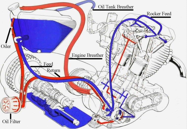
The oil filter serves a dual purpose, as it also protects the engine by retaining a small amount of oil when the car is turned off. Does anyone know the flow route through the oil filter on the old d series engines (suspect it's the same for b's etc). Any further suggestions are still appreciated, i. Stream flow rates and compositions;
Process flow diagram and filter design methodology exploring the process flow diagram the process flow diagram shown in the following figure lists the steps and shows the order of. A pfd does not show minor components, piping. Aid used to clarify, prior to the definition of a control or preparing a computer program, the. The diagramming community is gaining steam and we are fine tuning the features to make it more awesome.
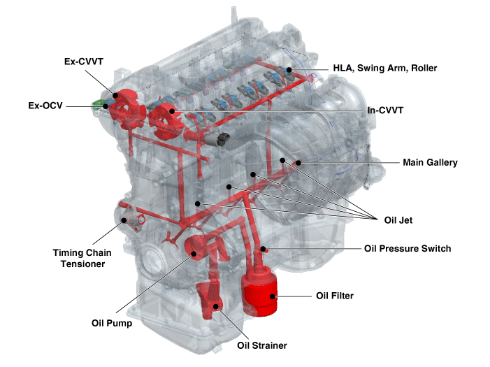
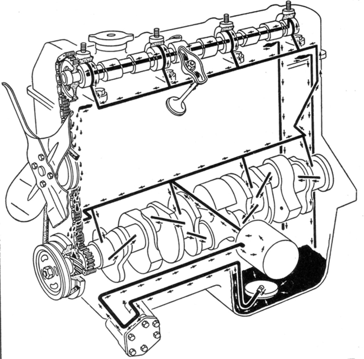
K&n® oil filters are designed to meet or exceed oem requirements, and are rigorously tested for efficiency, capacity, and burst strength. Filtering out the qualified customers from the less qualified is a hard task to begin with! The oil is pumped to all the crankshaft and rod bearings, cam shaft bearings, valve lifters, upper cylin. Get tips for process flow diagrams and try our templates with a free account!
Process flow diagrams (pfds) are used in chemical and process engineering. The pfd is a diagrammatic representation of the process. Primary separation on platform ( off shore). This is a schematic process flow diagram of the processes used in a typical oil refinery.
Pfd also tabulate process design values for components in different operating modes, typical minimum, normal and maximum. Data flow diagram has never been easier. Start a free trial today! Create process flow diagram online with visual paradigm's powerful process flow diagram tool.
Vp online is the best process flow diagram software because it offers a rich set of powerful editing features and symbols that suit different industries and purposes. Process flow diagram (pfd) illustrates the arrangement of the equipment and accessories required to carry out the specific process; I am wanting to know if the oil pump, pumps the oil through the threaded post into the filter or if it goes through the outer rim of. These diagrams show the flow of chemicals and the equipment generally, a process flow diagram shows only the major equipment and doesn't show details.
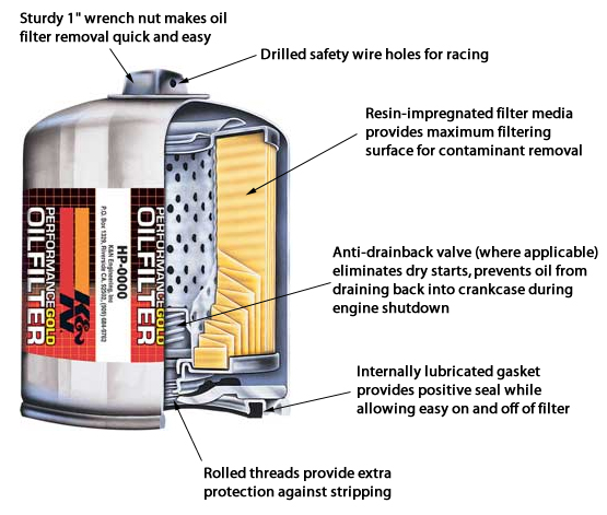
Find this pin and more on the industrial world by ed strayer. Review symbols and learn about best practices. Because the oil filter is typically located toward the middle or bottom of an engine, this rubber valve has a flap that blocks oil from draining back into the filter the porous filter medium consists primarily of microscopic cellulose fibers along with synthetic fibers such as glass and polyester, which increase. As oil flows through the oil filter media contaminants are trapped on it over time.
To enlarge the diagram above, click on the image. This is because each hydraulic. Not for remote filter mount applications. Coolant flow diagram for tn1.
If you're creating public diagrams make sure to rate them as well as diagrams submitted by other users. Coolant flow diagram for tn1.


