Bending Moment Diagram Triangular Distributed Load

For The Beam With Loading Shown Below Determine The

Solved Sum The Moments Acting About Support B To Calculat
Solution To Problem 417 Shear And Moment Diagrams Mathalino
This video shows how to solve beam with triangular load.
Bending moment diagram triangular distributed load. Distributed load is that acts over a considerable length or you can say over a length which is measurable. When you bend a ruler, even though apply the forces/moments at the ends of the ruler, bending occurs all along the. Since there are no other loads applied between the first and second cut, the bending moment equation will remain. If the deformed shape resembles that shown in the sign convention above then the sign of the bmd will.
After each successive change in loading along the length of the member, a fbd (free body diagram) is drawn previous definitions developed for shear forces and bending moments are valid for both beam and. Bending moment due to a uniformly distributed load (udl) is equal to the intensity of the load x length of load x distance of its center from the point of moment as shown in the following examples. This cut is made just before the second force along the beam. Derivation of this relationship is done in the integration of load equation.
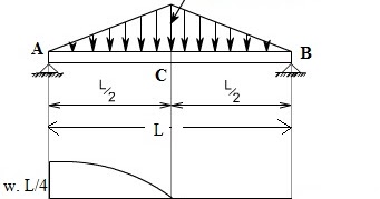
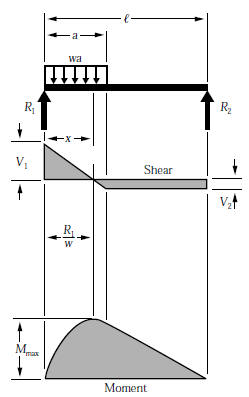
Bending moment is wl/4, where w is load, l is effective length. If the distributed loading is a curve of degree n, the shear will be a curve of degree n+1. The bending moment at the section is found by assuming that the distributed load acts through its center of gravity which is x/2 from the section. Bending moment diagram example 56:
Sketch the shear force and bending moment diagrams and find. Assign àframe loads àdistributed loads. 3 basic bending moment diagram. To construct a moment diagram.
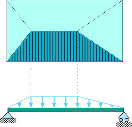
Deriving the shear force and bending moment equations for a beam with a triangular load. In probability theory and statistics, the triangular distribution is a continuous probability distribution with lower limit a, upper limit b and mode c, where a < b and a ≤ c ≤ b. The distributed load can be split into two parts, a rectangular and triangular shape. We now obtain the reactions ax, ay, and cy from the equilibrium equations.
Constructing shear and moment diagrams areas and thus after you finish passing over the width of a distributed load, the value of the shear diagram will have 5) you can tell if a triangular load diagram should turn into a skinny parabola or a fat parabola by. Trapezoidal load is that which is acting on the span length in the form of trapezoid. Shear force and bending moment diagrams for different beams subjected to concentrated loads, uniformly a triangular block of brickwork practically imposes such a loading on a beam. Bending moment at the fixed end = 10 x 2 x 1= 20 knm.
I understand the bending moment diagrams for a uniform distribution, and partially for a triangular distribution, however i am struggling to link the two for a trapezoid shape distribution. What is a distributed load? Bending moment refers to the internal moment that causes something to bend. Shear and bending moment diagrams are analytical tools used in conjunction with structural analysis to help perform structural design by determining the value of shear force and bending moment at a given point of a structural element such as a beam.
In this second shear and moment diagram video, i show how to calculate shear and moment diagrams for a variety of loading. For simple structures you can obtain the sign of the bending moment by thinking of the deformed shape. 5 uniformly distributed load (udl). Displayà show load assign à frame/cable/tendon on the pop up window click make sure that show joint loads with span loads and show span loading values.
Problem 868 determine the values of eiδ at midspan and at the ends of the beam loaded as shown in problem 847 compute the moments over the supports and sketch the shear diagram for the continuous beam shown in fig. Bending moment will be zero(0). Draw the bending moment diagram. Calculating bending moment diagrams by hand.
I have a problem which involves me drawing the bending moment diagram for a trapezoidal distributed load. Draw the shear force diagram. Also, pqrstu is the bending moment diagram drawn on a base pu, m being proportional to the vertical ordinates. Relations between distributed loads and internal shear forces and bending moments.
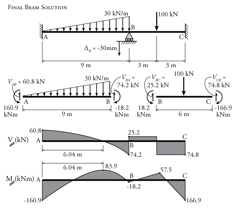
Relations between distributed load, shear force, and bending moment. The diagram depicting variation of bending moment and shear force over the beam is called bending. The bending moment diagram may also be constructed using the above relationships, namely, the bending moment varies linearly over unloaded lengths of beam and parabolically over lengths of beam carrying a uniformly distributed load. The change in the bending moment is equal to the area under the shear diagram.
Shear and bending diagrams 57 moving on, the video introduces with the triangular distributed loads and briefly demonstrates how unlike the udl, in a triangular distributed load the centroid position is required to determine in order. • the magnitude of the resultant force is equivalent to. We had a tutorial similar before but this. Ø consider the beam shown below subjected to an arbitrary loading.
• a load applied across a length or area instead of at one point. Cantilever beam calculation carrying a uniformly distributed load and a concentrated load. The direction a bending moment diagram is drawn depends on the sign convention being used. Also, the change in bending moment between two sections of.
The shape of bending moment diagram is parabolic in shape from b to d, d to c, and, also c to a. Left click on the frame: Therefore, the distributed load q(x) is statically equivalent to a concentrated load of magnitude q placed at the centroid of the area under the q(x) diagram. Structural axial, shear and bending moments.
For the distributed load to show select: For complex beams with more than a couple loads, determining moment and shear diagrams is very. • a distributed load can be equated with a concentrated load applied at a specific point along the bar. To complete a shear force and bending moment diagram neatly you will need the following materials.
Is represented by ab and acts through the. We have already noted in eqn. In strength of material, u studied shear force and bending moment diagram for static load ( load position is fixed) but influence line diagram is used to draw shear force diagram and bending moment. Trapezoid is generally form with the combination of uniformly distributed load (udl) and triangular.
Gallery of Bending Moment Diagram Triangular Distributed Load

Mechanics Ebook Shear And Moment In Beams
Triangular Load Mathalino

Solved The Cantilever Beam Ab Shown In The Figure Is
Shear Force And Bending Moment Diagrams For A Simply

Lecture 23 And 24
Beam Formulas With Shear And Mom

Bending Moment Diagram An Overview Sciencedirect Topics

Isosceles Triangle Load Moment Diagram Page 1 Line 17qq Com

A Cantilever Under Linear Distributed Load The Shear Force
9 4 The Slope Deflection Method For Beams Learn About

Lecture 23 And 24
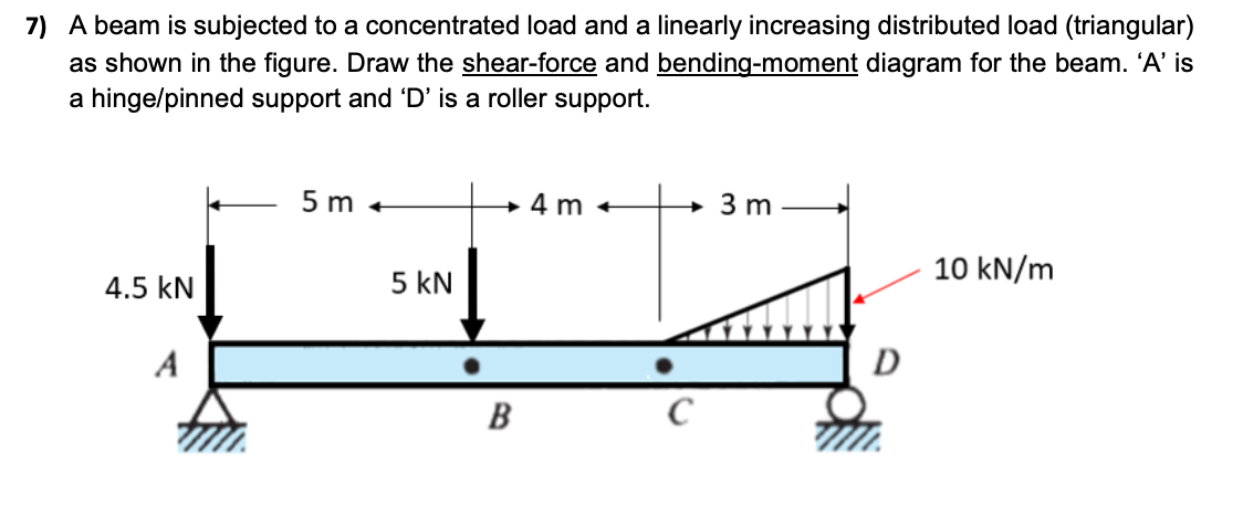
Solved 7 A Beam Is Subjected To A Concentrated Load And
Chapter 4 Internal Forces In Beams And Frames In

Shear And Moment Diagram Example 2 Mechanics Of Materials And Statics
Simply Supported Beam Calculator Calcresource
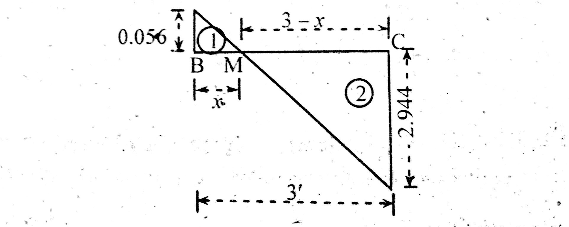
How To Locate Point Of Zero Shear Maximum Bending Moment
Solved Sketch The Shear And Bending Moment Diagram For Th
