Mercruiser Trim Wiring Diagram
This wiring provides electrical connections for the remote control's trim and neutral start circuits through the 14‑pin data mercury mercruiser and mercury outboard share a common smartcraft architecture.
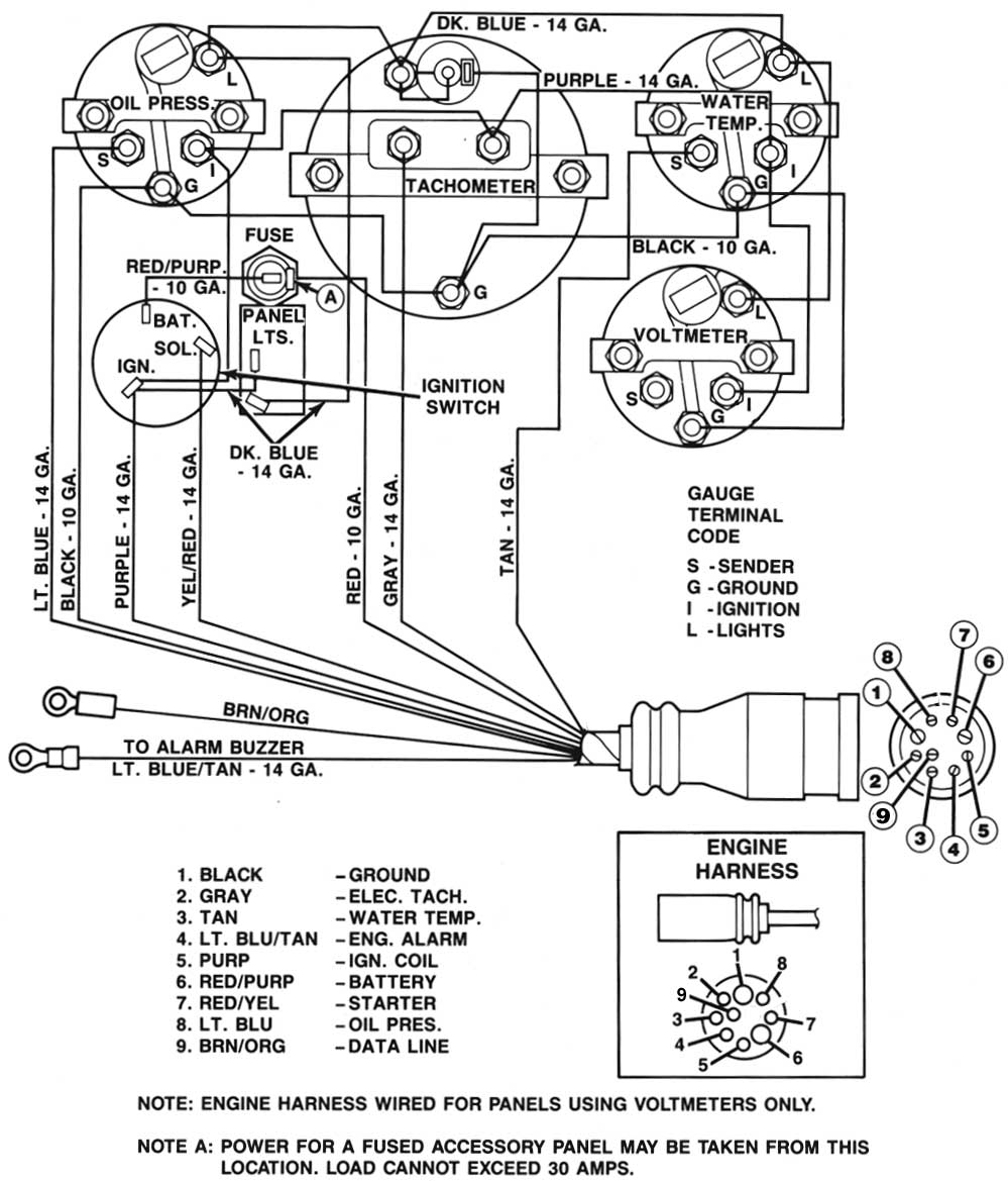
Mercruiser trim wiring diagram. The main chapters in a mercruiser engine repair manual include (engine. Remove and clean all connections to all batteries , sounds like a bad ground,power trim wires are only thing getting a good connection. Drive trims down but not up. Refer to instrumentation wiring diagrams for specific wiring diagrams.
Sometimes, the wires will cross. I need help page great for newer boat mechanics. Wiring diagrams for the qsb10/12/2013. Hundred of drawings, exploded views, photos and tables.
Mercruiser tilt and trim problems. Some models may also be equipped with a trim indicator sender. Introduction of the first mercruiser (standard production) efi engine: And limit sensor wiring diagram for power trim on a mercruiser.
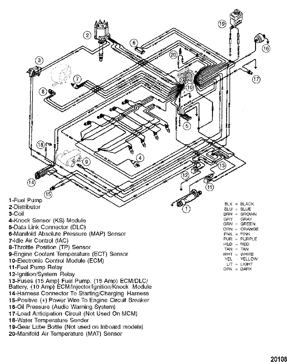
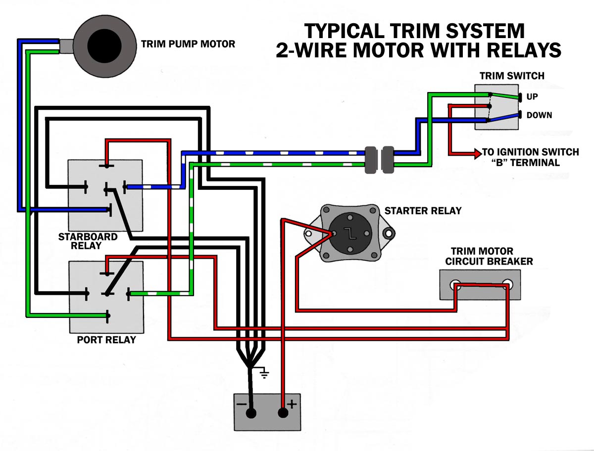
Ground , and the other sender black to harness brown/white to (from). Also, you can try swapping the wiring as shown below in the following diagram: Before you tear anything apart or replace wiring and switches, test it out. Looking for a wiring diagram for a 3.0lx alpha one.can anyone help please.
Power trim with push button (early). Where is a wiring diagram for 2008 4.3 l mpi mercruiser? This replaces mercruiser p/n 805320a1. Simple to follow illustrated procedures.
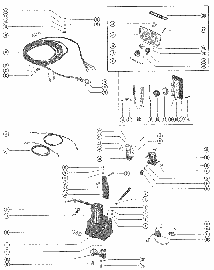
140 mercruiser wiring diagram schematic wiring diagram from mercruiser tilt trim wiring diagram , source:parts.36.otkupautomobila.co. It cannot be used on boats which have dual station gauges, such as 1 in the cockpit & 1 more on the fly bridge. Mercruiser power trim system wiring schematic. How to test your tilt and trim pump.
This engine had an aluminum block with cast in iron cylinder sleeves and was created by mercruiser and cast like mercury outboard engines. Buy the products and parts you need. Cummins mercruiser diesel wiring diagram.txt. It also contains critical specifications and a troubleshooting guide.
It will fit all mercruiser #1 drives made from 1975 to date including alpha one, gen ii and bravo. The diagram offers visual representation of a electrical according to earlier, the traces at a mercruiser trim sender wiring diagram signifies wires. Mercruiser service manuals from wholesale marine feature troubleshooting, diagrams, specifications and more. Mercury mercruiser #33 pcm 555 diagnostic service manual + wiring diagrams [pdf, eng, 10.6 mb].pdf.
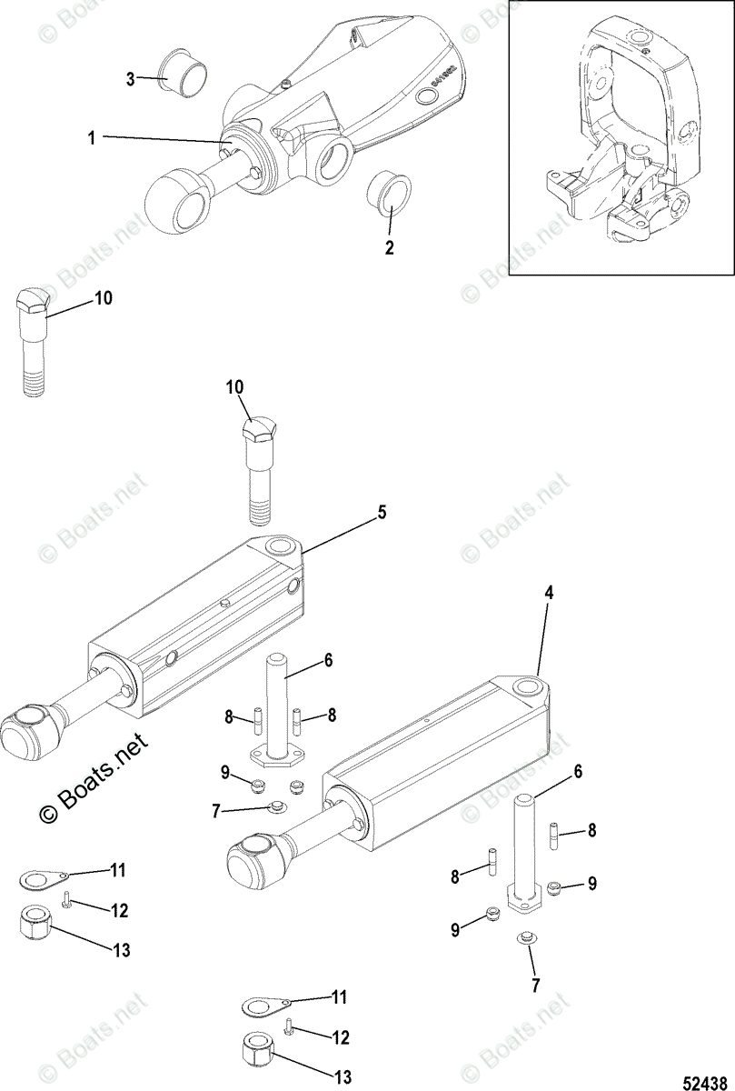
2005 dodge neon fuel pump. This diagrammed trim sender connection may or may not be the same for your year model but it appears to show one sender black sender wire going to harness black to neg. Click on links for model pages with spec sheets, manuals, etc. Mercruiser lower unit components diagram and photos.
1995 jeep cherokee radio wiring diagram. A mercruiser repair manual is a book of instructions that teaches you how to maintain, fix or restore the inboard engine or outdrive unite back to factory specifications. I need the color of the wires for a mercruiser 5.0 alpha one ignition. Please note the 1981 and up models use different lines.
Wiring diagrams, l engine wiring diagram (breaker points ignition). Troubleshooting, specifications and wiring diagrams. Connect the trim position sender wires from the transom assembly to the engine. Bennett trim tabs & accessories.
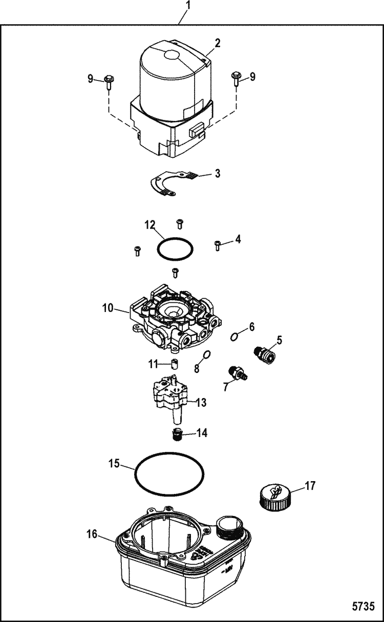
Trim hoses are manufactured by sierra marine. Mercruiser tilt and trim repair. Mercruiser wiring harness diagram for 5.0 / 5.7 alpha and bravo with ect mercruiser 5.0l 5.7l 6.2l 350 cid bravo dts electrical wiring harness diagram. Mercruiser power trim system wiring diagram at performance product technologies/ishopboating.com.
