Mercruiser Trim Sender Wiring Diagram

Diagram Mercruiser Trim Gauge Wiring Diagram Full Version Hd

Diagram 2 Wire Power Trim Wiring Diagram Full Version Hd

Trim Sender Wiring Diagram Box Wiring Diagram
After wires are disconnected, remove them from clamps or service manual number 26.
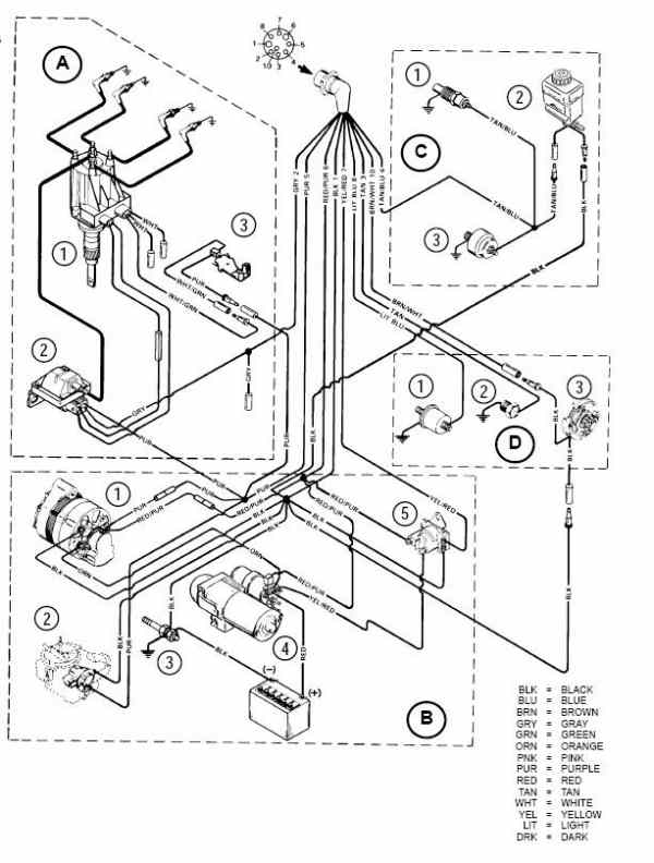
Mercruiser trim sender wiring diagram. Mercruiser service manuals from wholesale marine feature troubleshooting, diagrams, specifications and more. A wiring diagram is a streamlined standard photographic representation of an electrical circuit. Efi/mpi fuel pumps • first smartcraft capable mercruiser. Disconnect bullet connectors of trim sender wires (coming from transom assembly) from engine harness.
Looking for a wiring diagram for a 3.0lx alpha one.can anyone help please. The table of contents of the clymer® mercruiser® service manual is as follows I need help page great for newer boat mechanics. Connect trim sender wires and mercathode a.
Power tilt and trim wiring wiring diagram schematic name mercruiser trim sender wiring diagram the diagram offers visual representation of a electrical arrangement. Mercruiser 3.0l engine wiring diagrams. Before you tear anything apart or replace wiring and switches, test it out. Read more about replacing your gimbal bearing and ujoint.
- 2000 Ford Ranger Rear Drum Brake Diagram
- 2000 Gmc Sierra 1500 Radio Wiring Diagram
- 2004 Chevy Tahoe Brake Line Diagram
Earlier models with trim the sender wire connection at the mercathode controller: Drive trims down but not up. We now have sei sterndrive units. Identify mercruiser outdrive parts with detailed drawings & photos.
I am installing a new engine and will be using merc's vessel view system so i have that harness which is basically plug and play/one wire. Mercruiser trim sender limit switches wiring diagram. Install trim limit switch wires and trim position sender wires. The trim sender leads must be connected to the brown/white and black leads.
Volvo penta is a registered trademark of volvo penta corp. 4 wiring diagrams mm.0x d note : Troubleshooting, specifications and wiring diagrams. Power trim wiring diagram blk d black blu d blue brn d brown gry d gray grn d green orn d orange pnk d pink pur d purple red d red tan d tan wht d white.
Gm is a registered trademark of. 859187a1 power trim sender assembly port mounted this is a genuine mercury marine factory oem part, not aftermarket please check our current stock level and order below or use the contact us form at the bottom of the. This replaces mercruiser p/n 805320a1. Also, you can try swapping the wiring as shown below in the following diagram:
Hundred of drawings, exploded views, photos and tables. Trim and tilt motors and parts for mercruiser sterndrives. Do not apply antifouling paint to mercruiser drive unit or transom assembly. Power trim wiring diagram a b c d e f g h.
The first component is emblem that indicate electric component from the circuit. Step by step instructions detailing how to remove a mercruiser bravo sterndrive to repalce the trim position sender and trim limit switches. Gry lead for use with service tachometer. Connect trim position sender leads from gimbal housing to leads from engine harness.
Trim sender to trim gauge. 36 efi wiring diagram injetor 7 dk u 0 injetor dk grn r 87a ide ir ontro (i) vve u/wht u mercruiser horn warning systems. Mercruiser ignition wiring diagram | free wiring diagram variety of mercruiser ignition wiring diagram. The trim sender wires may not have any color sleeve or if they do, one side will have a brown sleeve.
Replacing them is a pain as the legs have to come off, so it's a trip to the shop for the boat as i have no facilities to do it. Mercury mercruiser #14 service manual sterndrive units alpha one generation ii [pdf, eng, 24.7 mb].pdf. Index all dts 1.6 l 3.0 l 4.3 l 5.0 l 5.7 l 6.2 l engine. How to wire fuel gauge and sending unit complete explanation.
I need the color of the wires for a mercruiser 5.0 alpha one ignition. For mercruiser applications the leads labeled lanyard outboard are left disconnected and protected with weather caps and the leads labeled wiring for smartcraft gauges. This diagrammed trim sender connection may or may not be the same for your year model but it appears to show one sender black sender wire going to harness black to neg. There are two things which are going to be present in any mercruiser trim sender wiring diagram.
Mercury mercruiser #33 pcm 555 diagnostic service manual + wiring diagrams [pdf, eng, 10.6 mb].pdf. Ground , and the other sender black to harness brown/white to. Please help guys my husband took the switch out months ago because he lost the key and. I need help page to identify components with detailed drawings and photos.
Most motor wire harnesses have a brown wire with read more about shift cables at replacing your mercruiser alpha or bravo shift cable. Simple to follow illustrated procedures. The fastest and easiest way to troubleshoot marine electronic fuel injection systems.
Gallery of Mercruiser Trim Sender Wiring Diagram
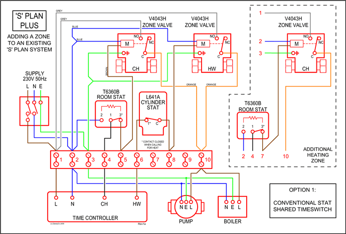
Diagram Mercruiser Trim Gauge Wiring Diagram Full Version Hd

Diagram 1989 35mercruiser Engine Wiring Diagram Full Version

Ha 5471 Pics Photos Wiring Diagram Of Mercruiser Alpha One

Diagram 3 0 Mercruiser Trim Wiring Diagram Full Version Hd

Diagram 4 3 Mercruiser Wiring Diagram Color Code Full

Zl 2648 Trim Sender Wiring Diagram Schematic Wiring

Diagram Alpha One Trim Wiring Diagram Full Version Hd

Diagram In Pictures Database Power Trim Wiring Diagram
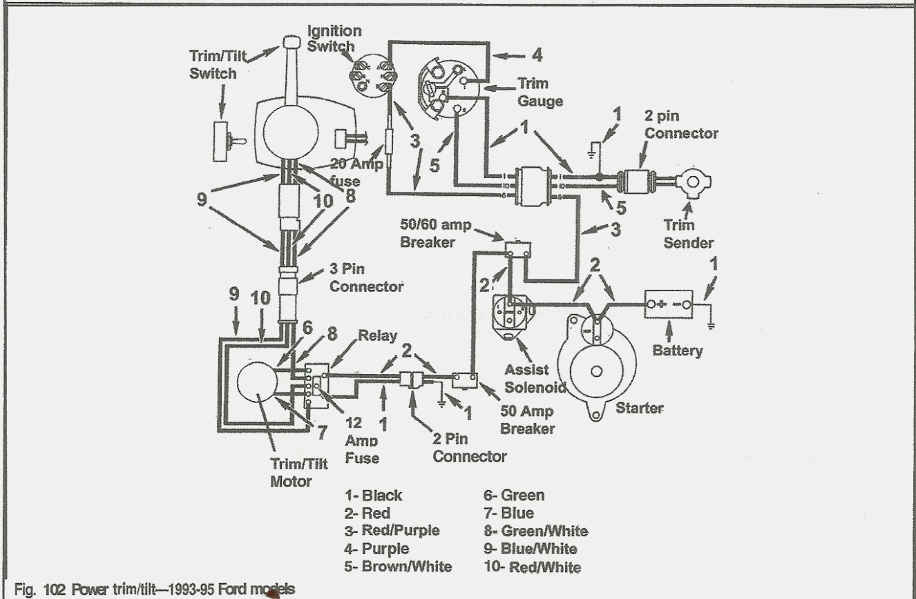
Diagram Mercruiser Trim Sender Wiring Diagram Full Version
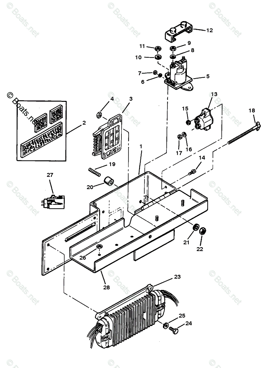
Diagram 1984 Mercruiser Inboard Electrical Engine Diagram
Mercruiser 3 0l Engine Wiring Diagram Perfprotech Com
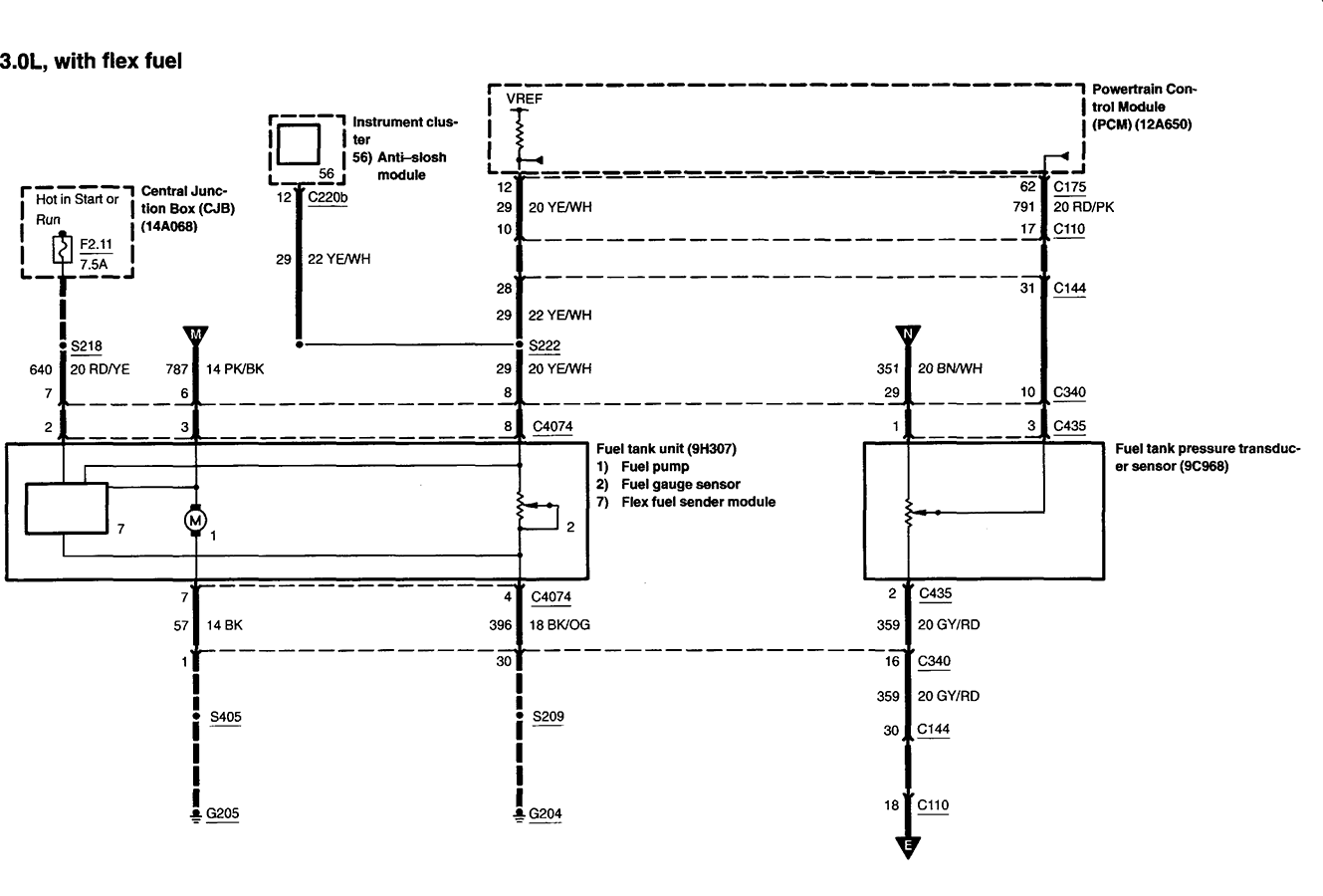
Diagram Pyrometer Sender Wiring Diagram Full Version Hd

Mercruiser 4 3 Wiring Diagram Luxury Cute Mercruiser Trim
Diagram Yamaha Outboard Tilt And Trim Gauge Wiring Diagram
Mercruiser Trim Sender Limit Wiring Help
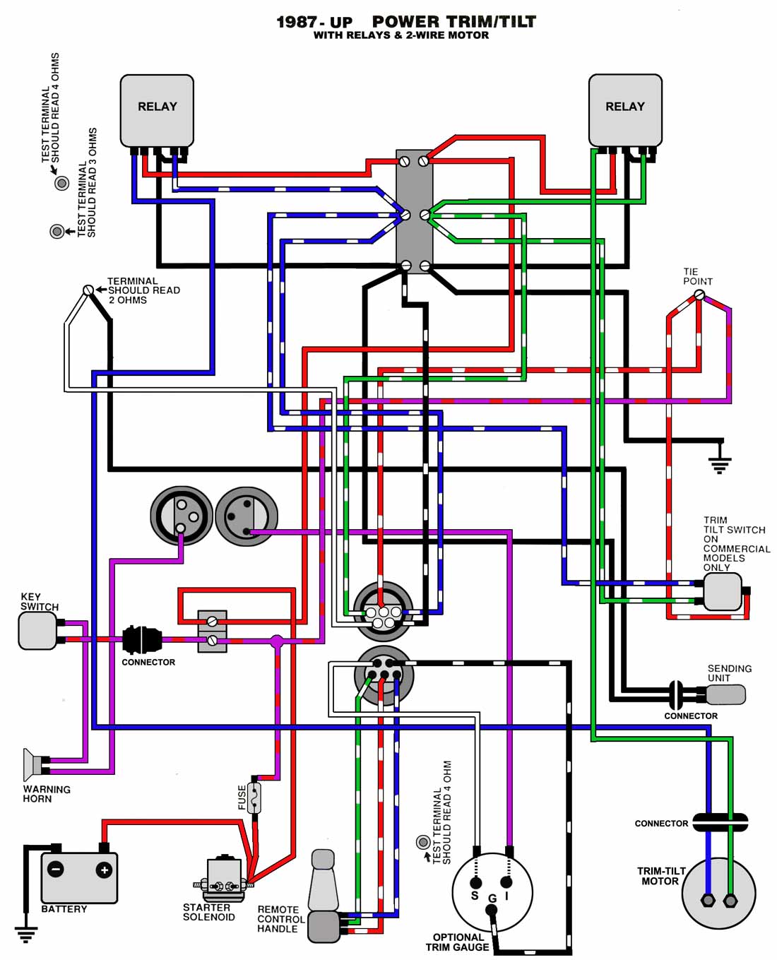
Diagram Mercruiser Trim Wiring Diagram Full Version Hd
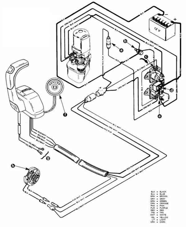
Diagram Power Trim Wiring Diagram Mercruiser Full Version Hd
