Mercruiser Trim Position Sender Wiring Diagram

Ed 1687 Trim Position Sensor Wiring Diagram Trim Senders
Mercruiser Trim Sender Wiring The Hull Truth Boating And

Diagram Fiat Bravo 2 Wiring Diagram Full Version Hd Quality
Disconnect trim position sender wires from engine wiring harness connections.
Mercruiser trim position sender wiring diagram. Disconnect trim limit switch wires and trim position sender wires. Gauge has never worked since i've had the boat. Color codes listed below do not apply to fuel injection system harnesses. Refer to water flow diagram for engine type being serviced.
.mercruiser digital trim sender wiring diagram, mercruiser trim position sender wiring diagram, every electrical arrangement is composed of there are two things which are going to be present in any mercruiser trim sender wiring diagram. Connect trim position sender wires (from transom assembly) to engine harness. Mercruiser 3.0l wiring diagram at performance product technologies/ishopboating.com. If a metul instrument panel la not used, each instrument gse must be power trim with trim sender (double solenoid system).
Can't find wires to connect to. Replacement parts warning electrical, ignition and fuel system components on mercruiser engines and stern drives are designed and manufactured to comply with u.s. Most relevant mercruiser trim limit sender wires websites. Mercury mercruiser #33 pcm 555 diagnostic service manual + wiring diagrams [pdf, eng, 10.6 mb].pdf.
- 2001 Dodge Dakota Wiring Diagram
- 1998 Ford Expedition Mach Audio Wiring Diagram
- Universal Windshield Wiper Switch Wiring Diagram
The main chapters in a mercruiser sterndrive repair manual include (important information, sterndrive unit, steering system, power trim. Disconnect bullet connectors of trim sender wires (coming from transom assembly) from engine harness. The table of contents of the clymer® mercruiser® service manual is as follows More than 30+ service & repair manuals for such sterndrive engines as mercruiser you can free download.
For mercruiser applications the leads labeled lanyard outboard are left disconnected and protected with this wiring provides electrical connections for the remote control's trim and neutral start circuits through the wiring for smartcraft gauges. It will fit all mercruiser #1 drives made from 1975 to date including alpha one, gen ii and bravo. The trim and tilt wiring. Wiring diagrams for yamaha golf carts valid wiring diagram for 2002.
Looking for a wiring diagram for a 3.0lx alpha one.can anyone help please. 2002 buick century fuel pump wiring diagram , 1998 chevy cavalier stereo wiring diagram , new holland ls180 starter wiring diagram , welding set diagram , 1995 ford mustang fuse box location , free hvac wiring diagrams , x18 pocket bike wiring. The newer model trim the trim sender wires may not have any color sleeve or if they do, one side will have a brown sleeve. It cannot be used on boats which have dual station gauges, such as 1 in the cockpit & 1 more on the fly bridge.
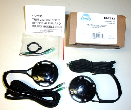
Power trim system wiring diagram. 822573a12 sender kit power trim this is a genuine mercury marine factory oem part, not aftermarket please check our current stock level and order below or use the contact us form at the. All formats available for pc, mac, ebook readers and other mobile devices. See wiring diagram at the end of this section for wiring connection points.
Related with mercruiser trim gauge wiring. Download mercruiser trim sender wiring diagram for free. If installing on boat that is equipped with merruiser stern drive, rown/white wire is connected to trim sender terminal block. With the drive in the full down position you will install the switches being careful not to misalign.
Connect multimeter leads to trim position sender wires. Mercruiser trim/tilt wiring for the position sender, the diagram shows one side to ground, and the other side to a brown/white wire, that goes to the connector, and on up to the trim gauge. Caution excess water in bilge can damage 2. Measuring resistance between these wires and ground may provide an answer.
Please help guys my husband took the switch out months ago because he lost the key and. Hundred of drawings, exploded views, photos and tables. I need the color of the wires for a mercruiser 5.0 alpha one ignition. Coast guard rules and regulations to minimize risks of fire or explosion.
Ground , and the other sender black to harness brown/white to. Connect trim position sender leads from gimbal housing to leads from engine harness. Look on the back of the gauge and see if there is a br/w wire there. Simple to follow illustrated procedures.
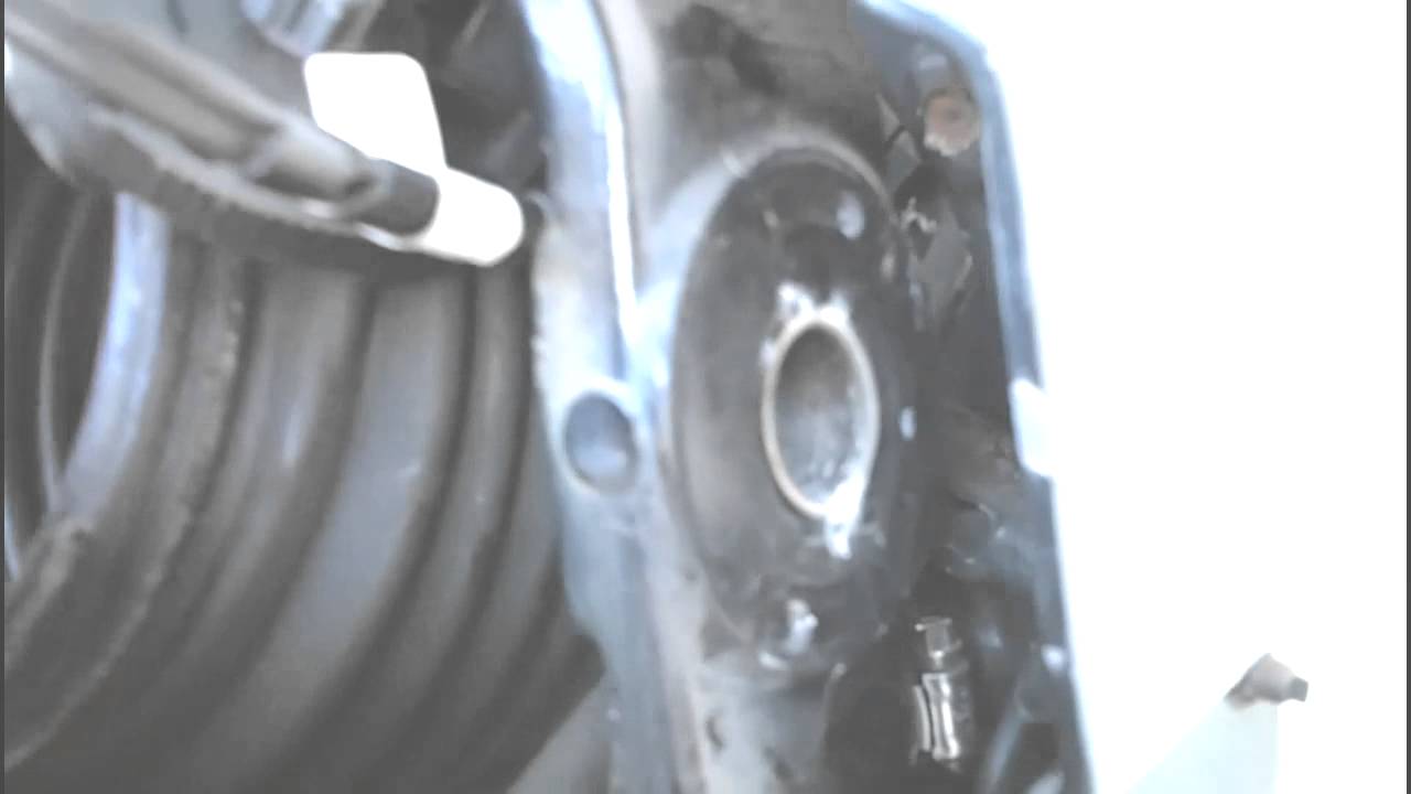
Mercruiser service manuals from wholesale marine feature troubleshooting, diagrams, specifications and more. Troubleshooting, specifications and wiring diagrams. Step by step instructions detailing how to remove a mercruiser bravo sterndrive to repalce the trim position sender and trim limit switches. That suggests both the gauge sender and limit switch are grounded inside the transom unit.
I took the power trim control apart and determined there was no power going to the up trim switch. Connect trim position sender wires (from transom assembly) to engine harness. This diagrammed trim sender connection may or may not be the same for your year model but it appears to show one sender black sender wire going to harness black to neg. A mercruiser repair manual is a book of instructions that teaches you how to maintain, fix or restore the inboard engine or outdrive unite back to factory specifications.
I did some diagnosing of the problem, and discovered the trim sender wire from the stern drive to the terminal block on the front of the engine had almost deteriorated from heat from the intake manifold.
Gallery of Mercruiser Trim Position Sender Wiring Diagram
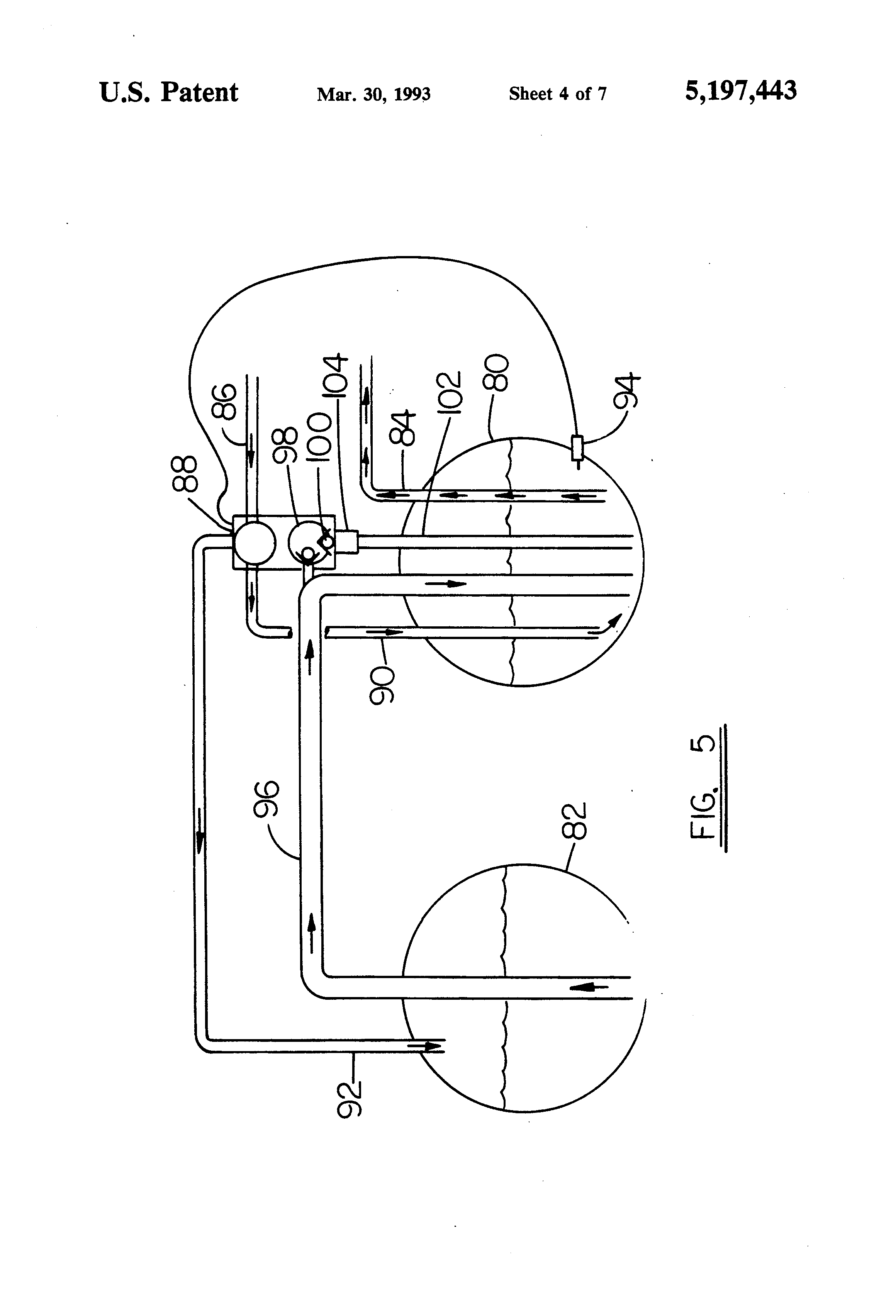
Diagram Fuel Sender Wiring Diagram Full Version Hd Quality
Diagram Tilt And Trim Wiring Diagram Full Version Hd Quality
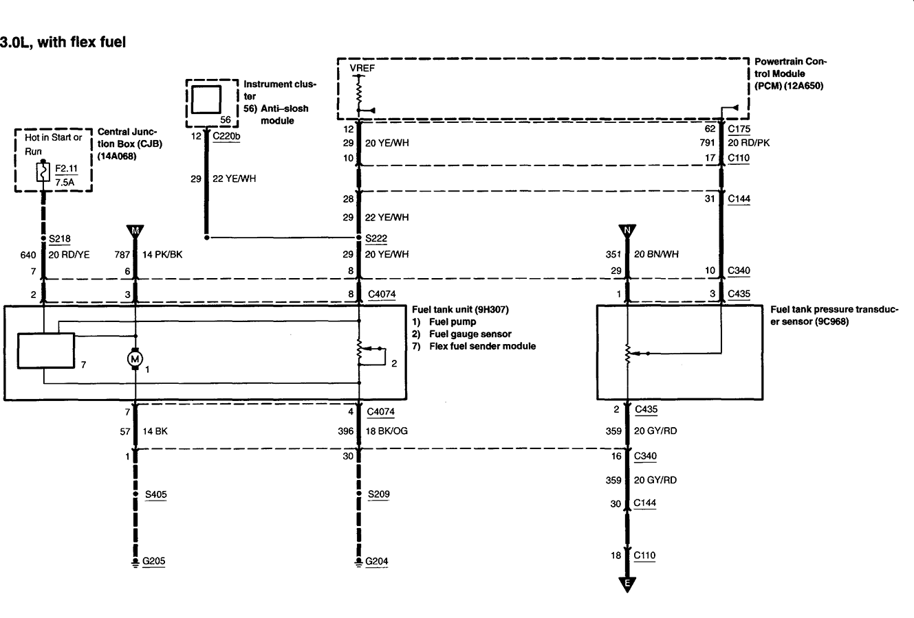
Diagram Vdo Senders Wiring Diagrams Full Version Hd Quality
Diagram Trim Sender Wiring Diagram Full Version Hd Quality
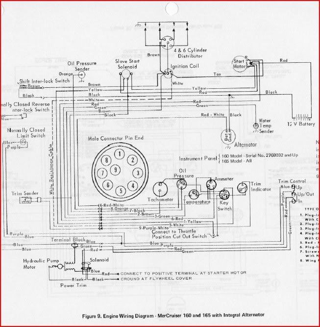
Diagram Engine Wiring Diagram For A 165 Mercruiser Full
Mercruiser Trim Sender Limit Switches Amp Wiring Diagram

Diagram Fuel Sender Wiring Diagram Full Version Hd Quality

Mercruiser Trim Sender Limit Switches Amp Wiring Diagram

Diagram 140 Mercruiser Wiring Diagram Schematic Full Version
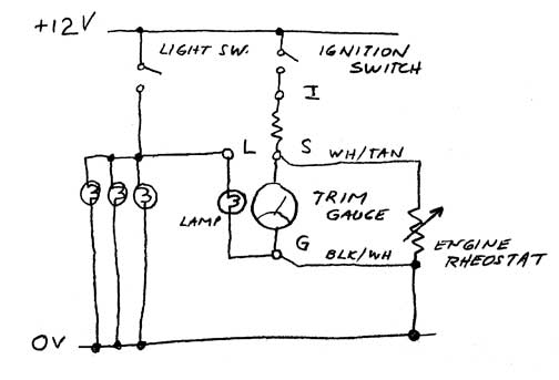
Diagram Mercruiser Trim Gauge Wiring Diagram Full Version Hd
Mercruiser Trim Sender Amp Limit Switch Replacement
Diagram Cmc Trim And Tilt Wiring Diagram Full Version Hd

Diagram How To Jump A Mercruiser Connector Wiring Diagram

Diagram Vintage Mercruiser Trim Gauge Wiring Diagram Full

Diagram Mercruiser Trim Sender Wiring Diagram Full Version
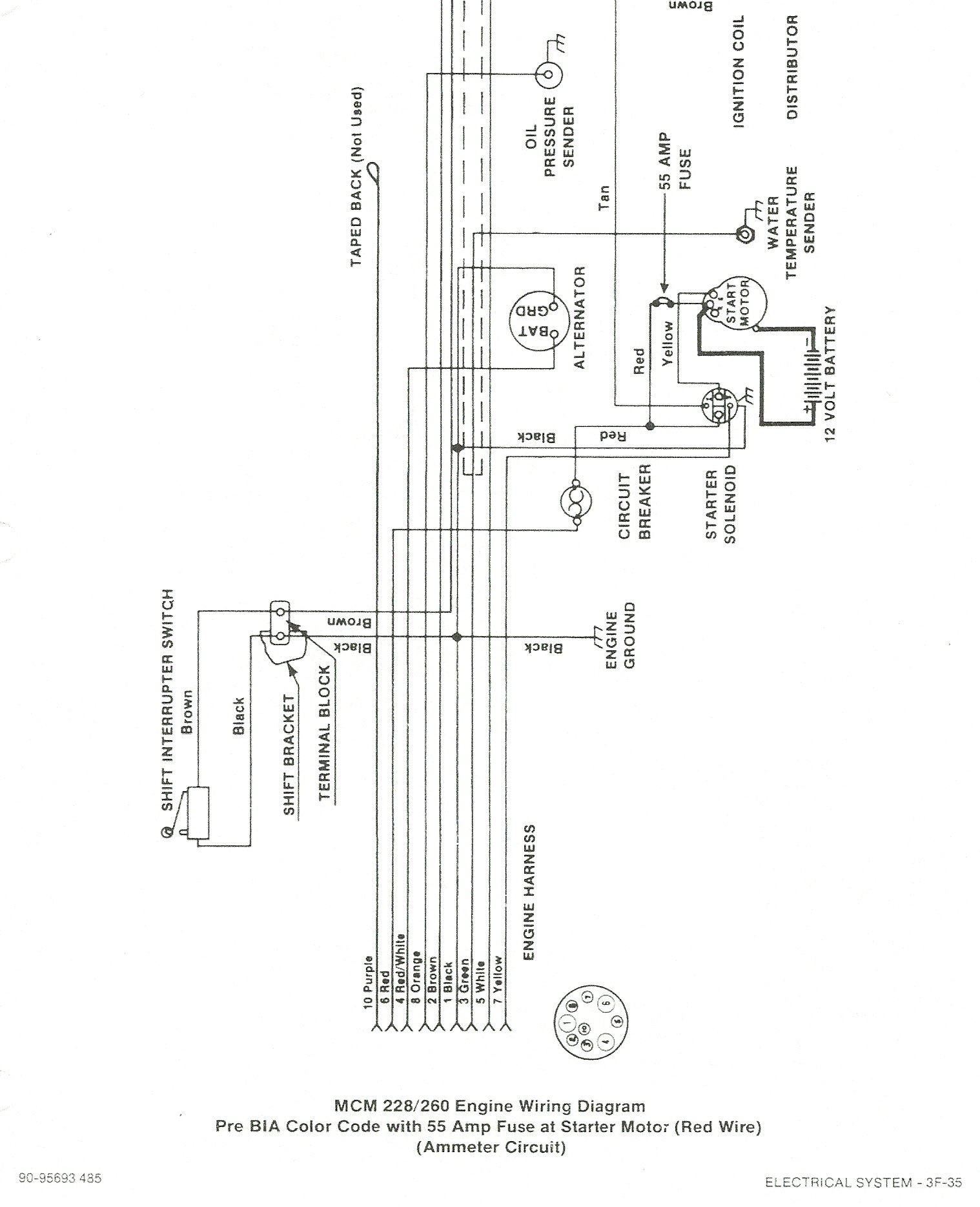
Diagram Mercruiser Trim Sender Wiring Diagram Full Version

Zy 5595 Mercruiser Gauges Wiring Schematic Wiring
