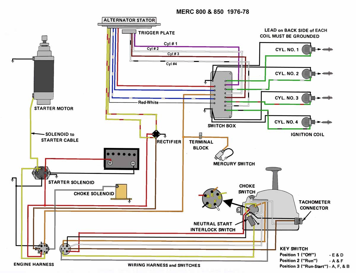
Mercruiser Trim Gauge Wiring Diagram
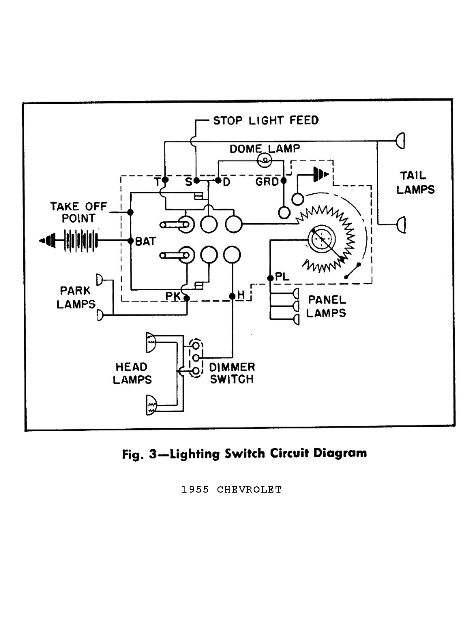
Instrumentation wiring diagram (battery meter circuit).
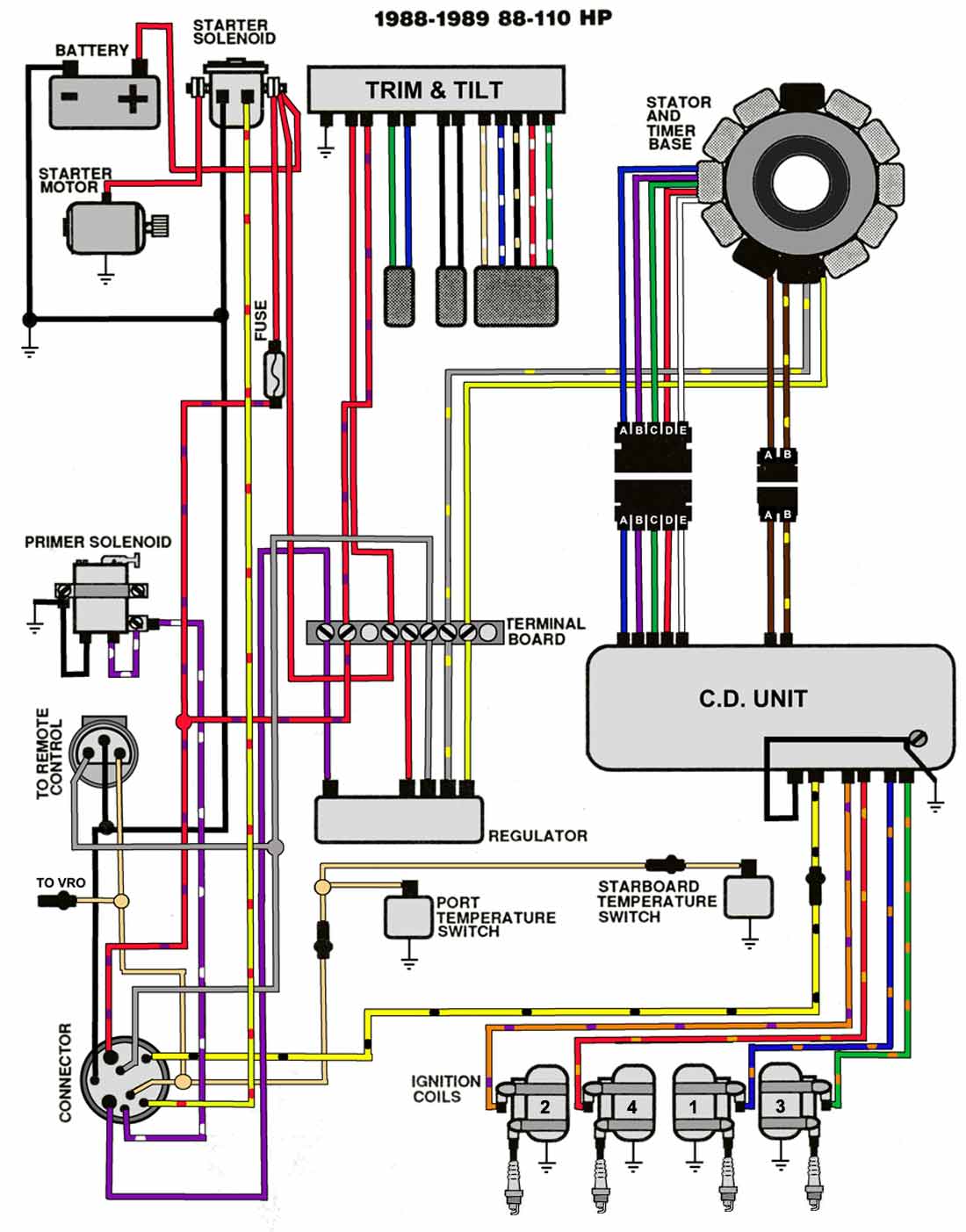
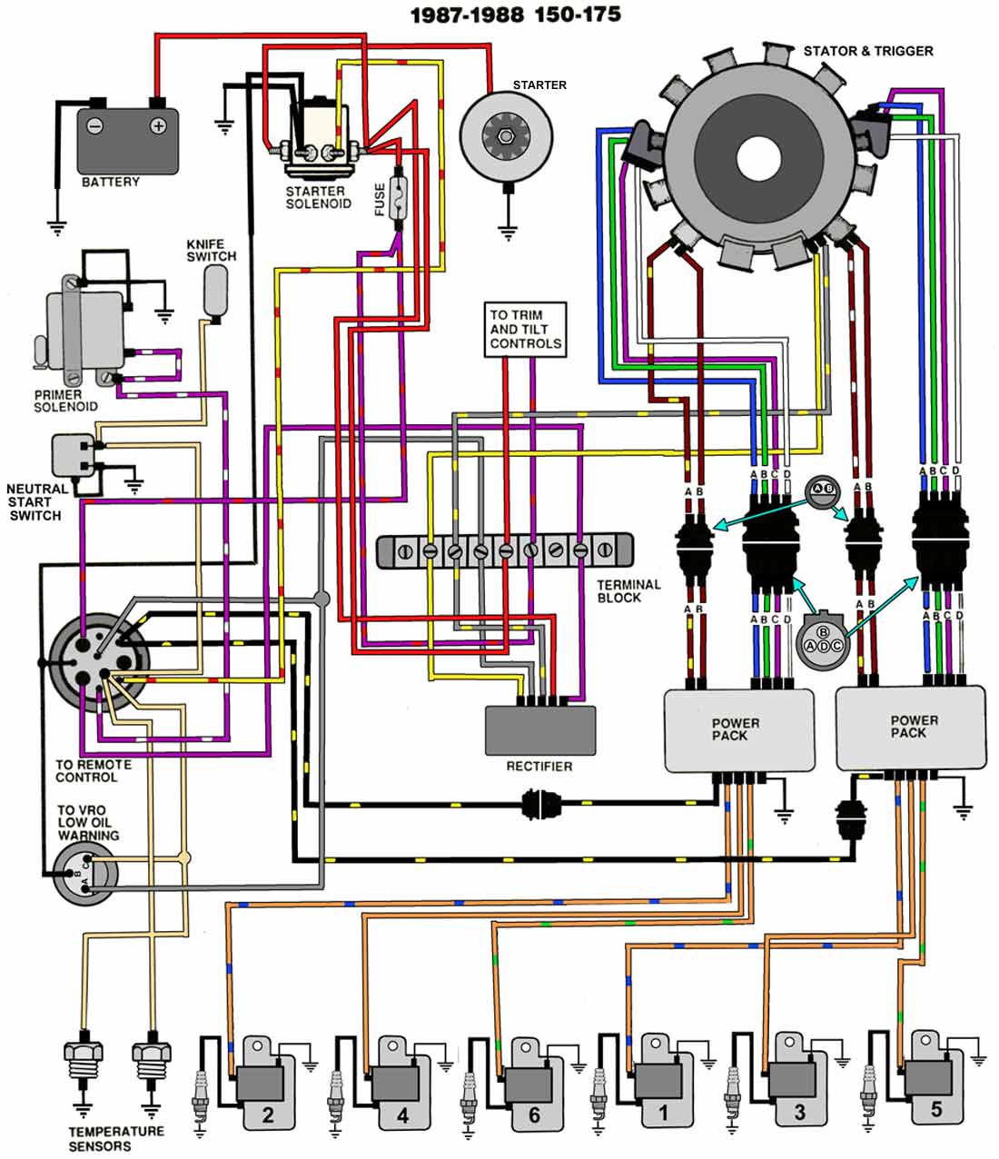
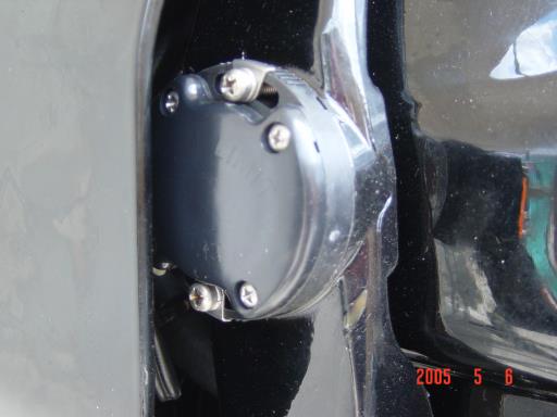
Mercruiser trim gauge wiring diagram. Mercury mercruiser #33 pcm 555 diagnostic service manual + wiring diagrams [pdf, eng, 10.6 mb].pdf. I believe what you are seeing is the limit switch for the trim. Index all dts 1.6 l 3.0 l 4.3 l 5.0 l 5.7 l 6.2 l engine model years starting sn ending sn fuel. Mercruiser power trim system wiring schematic.
Some models may also be equipped with a trim indicator sender. Mercruiser power trim system wiring diagram at performance product technologies/ishopboating.com. Gm is a registered trademark of. More than 30+ service & repair manuals for such sterndrive engines as mercruiser you can free download.
Tighten all fittings securely, but do not overtighten. I am installing a new engine and will be using merc's vessel view system so i have that harness which is basically plug and play/one wire. Years 1972 to 1983 illustration for troubleshooting your stern drive. I wanted to see if a trim gauge was easy to install, or if anyone knew the wiring colors and or locations?
Shop for genuine mercury smartcraft sensors, rigging kits, harnesses, gauges, interface kits, conversion kits, vesselview instruments and accessories, analog instruments, gauges, senders, monitors, transducers, active trim, trim position indicators and much more all at discounted prices. Thing is, i want to have the traditional round gauges as a back up so i purchased a 10 pin harness and would like to aug 3, 2013. Tilt and trim switch wiring diagram awesome technical information. Buy the products and parts you need.
This engine had an aluminum block with cast in iron cylinder sleeves and was created by mercruiser and cast like mercury outboard engines. The fastest and easiest way to troubleshoot marine electronic fuel injection systems. Tighten securely and coat with liquid neoprene to help control corrosion: Manual number 28 power trim electrical system note:refer to power trim system wiring diagram.
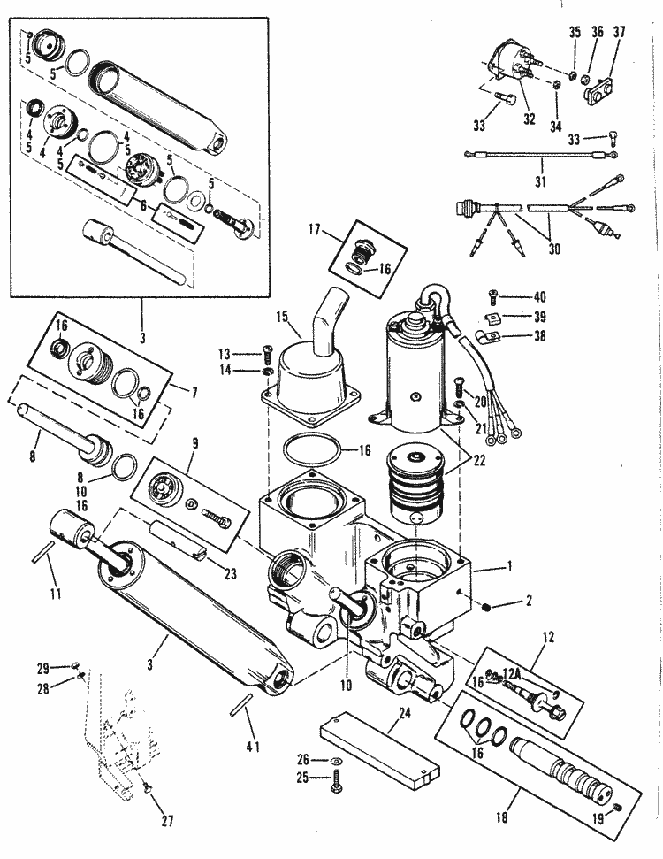
Power trim with push button (early). Simple to follow illustrated procedures. Mercruiser lower unit components diagram and photos. Following the wiring diagram for the mercruiser 2.5l trim pump (single solenoid) and i am having the hardest time getting it to work.
Diagram 2002 mercruiser 5.0 wiring diagrams 2002 mercruiser 5.0l 2002 mercruiser 5.0l ignition coil 2002 mercruiser 5.0l mpi wiring diagram 2002 mercruiser. Related searches for mercruiser trim gauge wiring mercruiser trim sender wiring diagrammercruiser tilt trim schematicmercruiser trim indicator wiring diagrammercruiser power trim wiring diagrammercury. A part of 454 mercruiser wiring diagram, but you will see that most manuals (a minimum of the useful omc 4.3 mercruiser 5.0l and. The linked images are printable but may print across more than 1 page (in order to be legible).
Troubleshooting, specifications and wiring diagrams. Alpha one has a switch on both the port side and starboard side of the drive when it has a trim gauge. Drive trims down but not up. Identify mercruiser outdrive parts with detailed drawings & photos.
Please help guys my husband took the switch out months ago because he lost the key and. Also, you can try swapping the wiring as shown below in the following diagram: Mercruiser service manuals from wholesale marine feature troubleshooting, diagrams, specifications and more. In consideration of these factors, mercury mercruiser has adjusted some maintenance intervals and arrange to have a technical service representative check the unit using a special gauge.
Smartcraft dts (digital throttle & shift) delivers precise and smooth handling displays that typically have a pointer and scale to indicate a specific measurement such as speed, rpm, trim, or fuel level. Hundred of drawings, exploded views, photos and tables. I'll attach the photos of i have a 2004 50hp tldi tohatsu when i try to start it the relay where the pos cable hooks up clicks and th ground wire gets real hot. When dry, slide neoprene sleeve over connection.
Before you tear anything apart or replace wiring and switches, test it out. Mercruiser trim/tilt wiring for the position sender, the diagram shows one side to ground, and the other side to a brown/white wire, that goes to the connector, and on up to the trim gauge. Click on links for model pages with spec sheets, manuals, etc. The can p (1) circuit (blue & white wires) connect the engine to this wiring provides electrical connections for the remote control's trim and neutral start circuits through the wiring for smartcraft gauges.
The diagram offers visual representation of a electrical according to earlier, the traces at a mercruiser trim sender wiring diagram signifies wires. Sometimes, the wires will cross. How to test your tilt and trim pump. I need the color of the wires for a mercruiser 5.0 alpha one ignition.
The table of contents of the clymer® mercruiser® service manual is as follows I need help page great for newer boat mechanics.

