Delco Bose Gold Series Wiring Diagram
This standard music systemis the delco' bose music system withdual playback.
Delco bose gold series wiring diagram. Gm delco products radio wiring interface / bose 91 seville p/n 22093491. You will definitely want to save delco car stereo wiring diagram to your desktop. 1998 chevrolet corvette car stereo radio wiring diagram radio constant 12v+ wire: If you don't see the audio radio wiring diagram you need comment and we will.
Bose gold amp repair $100, two or more $90 each lifetime warranty. The system includes an am and fm stereo electronically tuned radio receiver with an integral cassette, andsix delco@custom designed speakers with very. You are right that it could be the controls. 2003 acura tl car radio stereo wiring diagram.
The easiest would be to wire a 3.5 input to the orange and white wires with a it's for even older am delco radios, but it explains how to wire the 3.5 input. I will make a diagram to show everyone what i did. Manufactured to look just like the original, you'll have the looks of your corvette restored in no time. Variety of delco bose gold series wiring diagram.
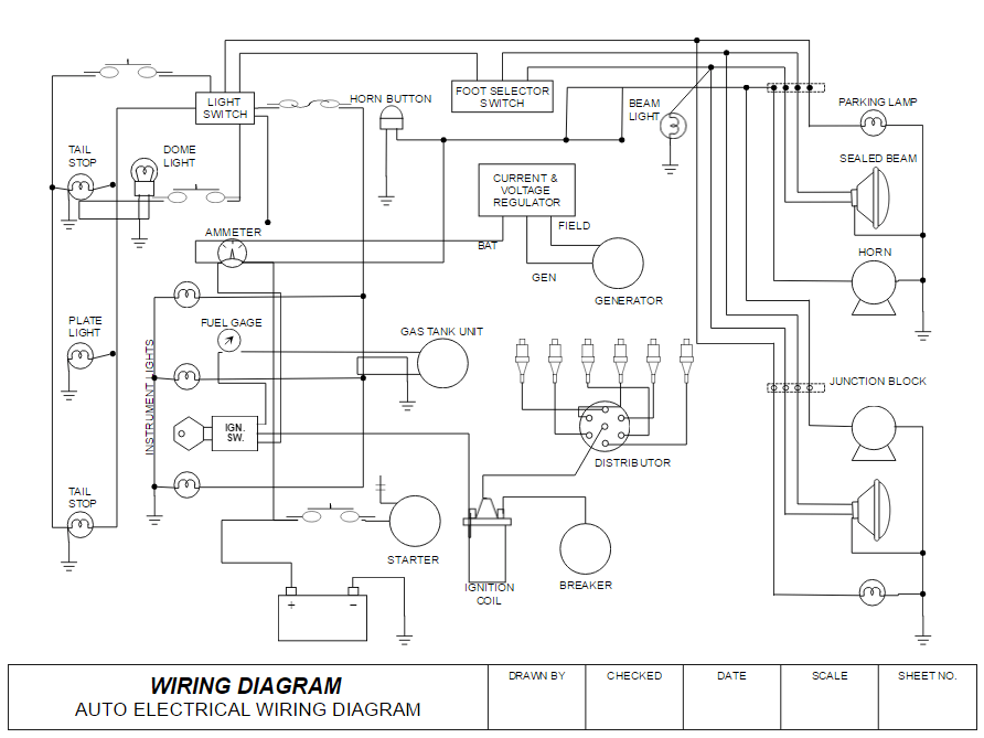
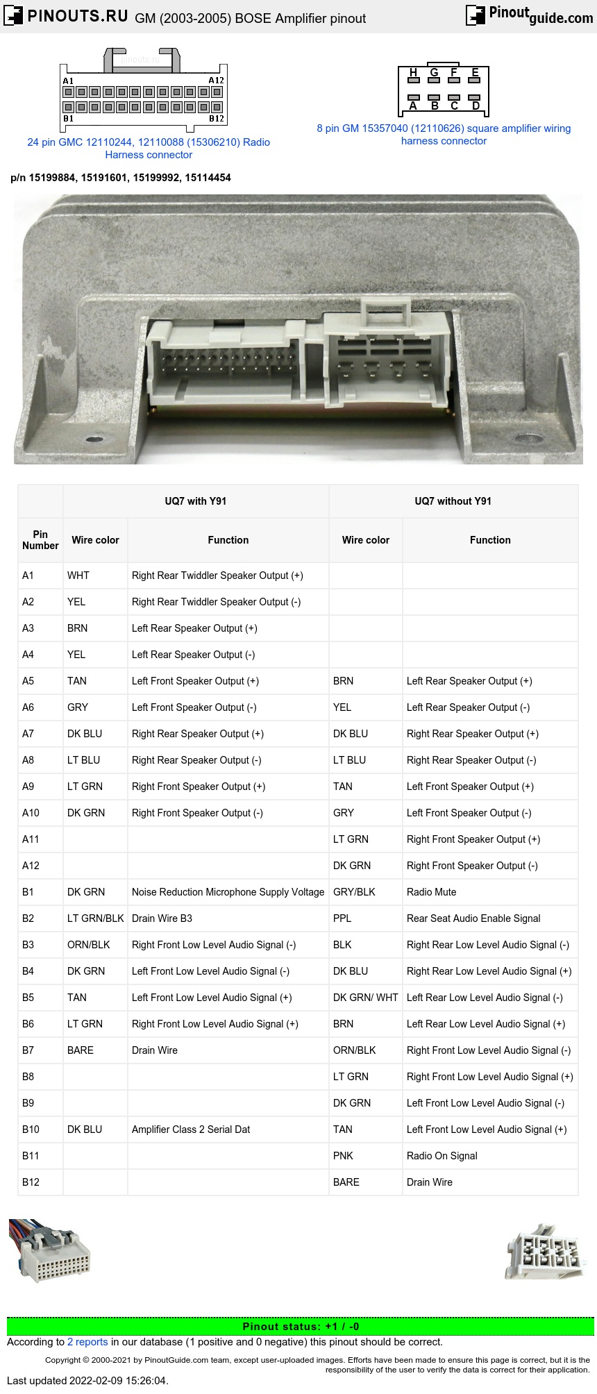
1992 bose gold #pn 16160761 #sn 1024246. I followed those instructions but when i got no spark, i continued doing research and found the third diagram. A wiring diagram is a simplified standard pictorial depiction of an electrical circuit. Is anybody able to tell me a decription of the two connectors and wiring ?
If you find any conflicting info please leave a comment with what you found in your mazda cx9. Bose owner's guide dvd home entertainment systems 321 series ii, 321gs series ii (80 pages). Bose wiring diagrams of bose audio system, mounted into some version of alfa romeo 147. Black you will have to get the schematic for your electrical system to locate the 12 volt trigger wire for the relay that turns on the delco/bose amp.
If you don't get the wiring harness to by pass the bose system and the amps, you'll have to rewire the whole system. Although the original bose system may not be capable of extreme bass, once. Not in a big hurry cause' i've got a bose system in everything i drive but i'll give it. How to unlock your theftlock, delco radio.
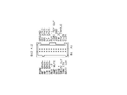
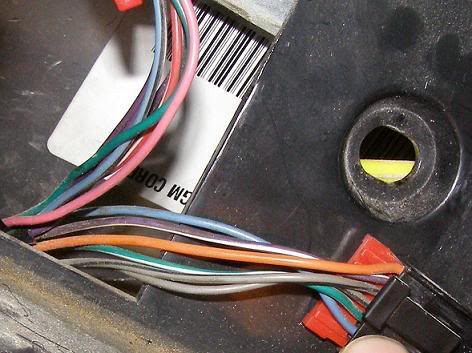
Especially this one on the picture to find speaker inputs and outputs. I have a delco bose gold series model #16083256 am/fm cassette cd i need the wiring diagram for it as i don't have the plugs in the car i wish to install it in to match the one's on the radio itself.… read more. Pc oscilloscope, digital oscilloscope, usb oscilloscope, digital multimeter, analog multimeter) by different manufacturers (fluke, wavetek, tektronix ) search our database of service manuals, schematics, diagrams, pcb design. Here's the colors i have in this harness.
I read your answer to the gentleman that had troubles identifying the colors on his delco bose gold series radio. Left low knob switch only betwen am or fm not tp or cd and ejct button work only if radio is off, in on. It reveals the components of the circuit as simplified shapes, as well as the power as well as signal connections between the gadgets. Orange radio switched 12v+ wire:
I used the battery, ignition, and ground for the cdm(reciever in the trunk) then wired them to 3 wires going to the orginal bose. I also communicated with the person who actually drew the second diagram and clarified which pins to use. Delco cassett stereo wiring color codes. 2000 dodge neon stereo wiring.
Changing the system is costly because all the components must be replaced and the wiring must be modified. Similar to how i've done other heads, here's how i added an auxiliary input to a delphi delco gm head. Read more about c4 bose woes: Audio path the audio path block diagram is as follows
Gold series amplifier repair rate $100 each with a lifetime warranty. The wiring diagrams don't show anything that makes me think you can just put a rca end on it and have your interconnect ready to connect into your at least thatch what the wiring diagram says, at least the actual mic it self it not connected to the head unit. *these wiring diagrams are specific to the fsip control that replaces the oem control. Bose speakers snap, crackle, pop, sizzle, high pitch squeal, distorted, low or no output.
5 pin din audio connector a wiring diagram is a streamlined traditional photographic representation of an electrical circuit. Click on the image to enlarge it or click here for the adobe.pdf version you can download and print.


