Mercruiser Trim Sender Wiring
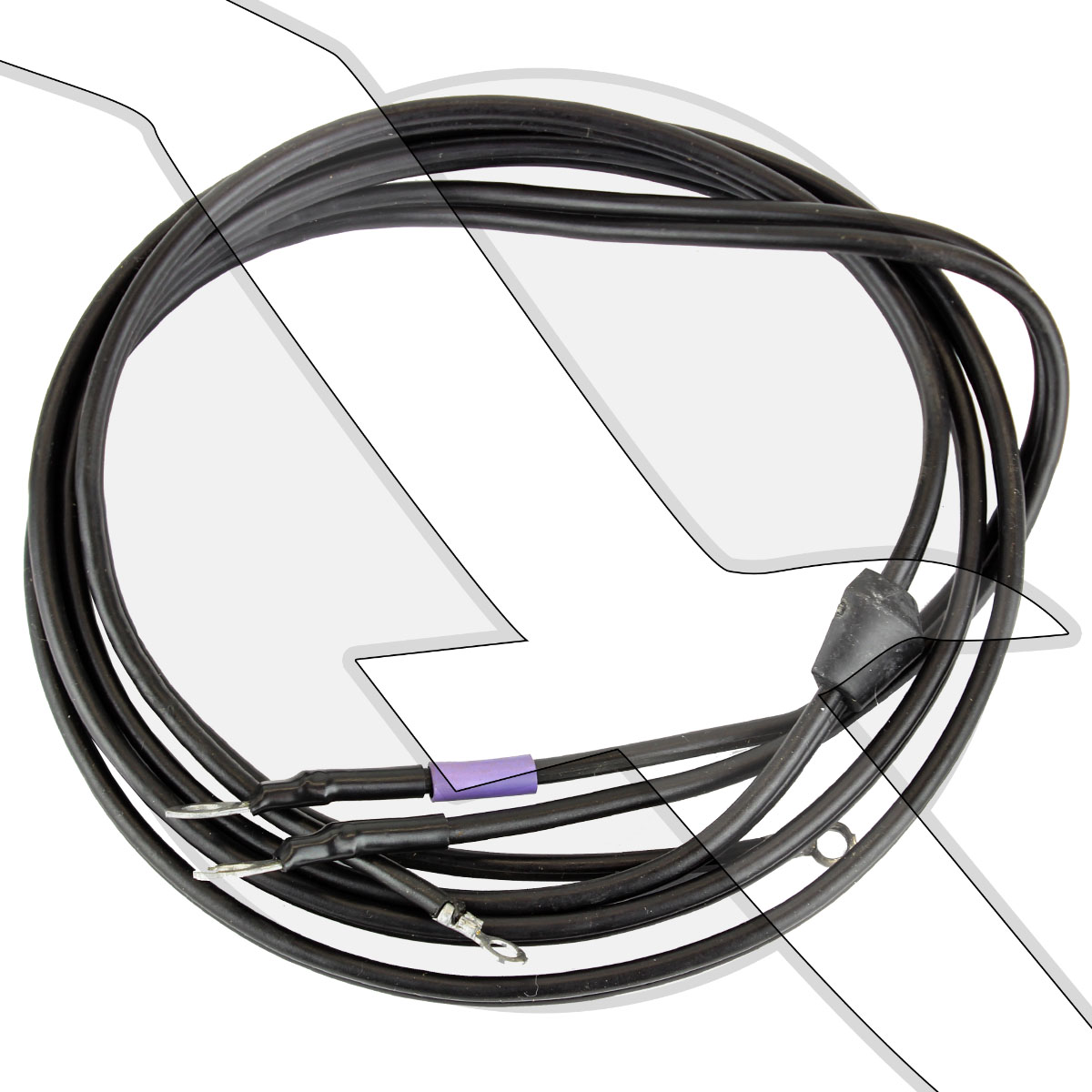
Details About Mercury Marine Mercruiser Transom Tilt Trim Sender Wire Harness 84 19216
Diagram Mercruiser Trim Gauge Wiring Diagram Full Version Hd

Diagram Fuel Sender Wiring Diagram Full Version Hd Quality
Packaged with quicksilver name on box.
Mercruiser trim sender wiring. Gauge has never worked since i've had the boat. Mercruiser power trim system wiring diagram at performance product technologies/ishopboating.com. The trim sender wires may not have any color sleeve or if they do, one side will have a brown sleeve. Models covered all 14‑pin mercruiser, cummins mercruiser diesel this wiring provides electrical connections for the remote control's trim and neutral start circuits paddle wheel speed sensors • depth transducers • fuel level senders • a few external.
Can't find wires to connect to. The trim position sender is the signalling device for the the trim gauge. Trim problems mercruiser 3.0 troubleshoot(read update in description). It will fit all mercruiser #1 drives made from 1975 to date including alpha one, gen ii and bravo.
Most motor wire harnesses have a brown wire with read more about shift cables at replacing your mercruiser alpha or bravo shift cable. Ask a question about this product. Trim tab hydraulic cyclinder rebuilds require specialized skills, knowledge and tools to successfully rebuild them. This replaces mercruiser p/n 805320a1.
The cam on the lower end of the shift shaft turns turns the shift crank, the lever on the there is no lock down latch on a mercruiser outdrive. Route new trim limit switch wires through hole. That suggests both the gauge sender and limit switch are grounded inside the transom unit. Best left to the pros.
The trim sender leads must be connected to the brown/white and black leads. 93%(27)93% found this document useful (27 votes). Disconnect trim limit switch wires and trim position sender wires. Connect trim position sender wires (from transom assembly) to engine harness.
Trim control wiring harness connector loose or corroded. Btw, the trim limiting system was introduced by mercruiser on their #ii drives, around 1969. The trim and tilt wiring. Savesave mercruiser service manual 6 outdrives r/mr/alpha o.
I have been trying to find a engine wiring diagram for a 500bull dog 540 v8 !990 throu 96. Color codes listed below do not apply to efi and mpi system harnesses. I need the color of the wires for a mercruiser 5.0 alpha one ignition. Replacing them is a pain as the legs have to come off, so it's a trip to the shop for the boat as i have no facilities to do it.
Mercruiser trim pump wiring wiring diagram. Mercruiser trim sender & limit switch replacement. Replaces oem mercury marine tilt trim switch kit 805320a03. Kit includes adapters for older style ring terminal connectors.
These wiring harnesses were designed for use in custom engine installations. Mercury mercruiser #33 pcm 555 diagnostic service manual + wiring diagrams [pdf, eng, 10.6 mb].pdf. The table of contents of the clymer® mercruiser® service manual is as follows For #1 drives thru alpha gen ii and all bravo drives.
Read more about replacing your gimbal bearing and ujoint. Hi i am about to install 2005 mercruiser 350 mag mpi s/n ow384791 what color wires do i pulg trim sender into. Bia color code and abbreviations. Efi/mpi fuel pumps with low pressure.
This is the kit for 1 drive, includes the trim sender & the trim limit switch. Trim sender to trim gauge. Power trim up limit goes through pcm 555 and a new relay. Fresh tilt and trim switch wiring diagram.
Look on the back of the gauge and see if there is a br/w wire there. Power trim with trim sender (double solenoid system). Wiring colors for mercruiser note: Bring together the two grommet halves and ensure they are seated tightly in the hole and that the flat edges that mate together are vertically aligned.
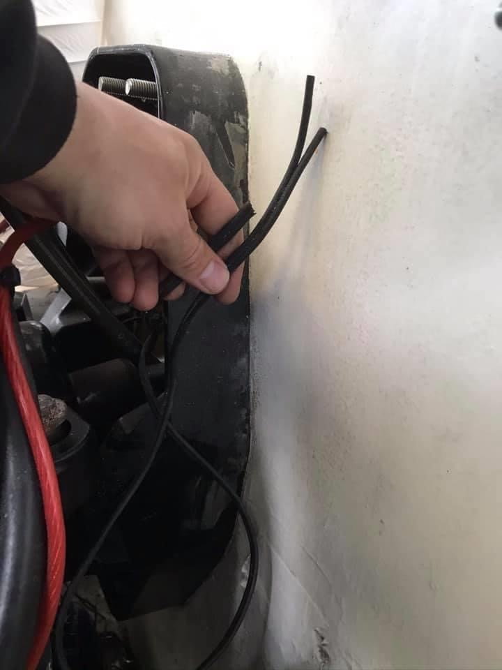
The resident boat service & repair professionals will have additional helpful information, suggestions and advice. In the physical drawing just two black wires come from the transom unit. Clean and secure connection 13 as necessary. Or do you have the standard 10 wire main harness that runs from the helm back to the engine?(this is the standard mercruiser harness).
In consideration of these factors, mercury mercruiser has adjusted some maintenance intervals and corresponding tasks to be performed. Mercruiser trim/tilt wiring for the position sender, the diagram shows one side to ground, and the other side to a brown/white wire, that goes to the connector, and on up to the trim gauge. Connected the trim sender wires from the lower unit to the brown/white and black wires which match the original wiring connections. My boat has twin mercruiser alpha 1 legs, the trim senders need replacing every couple of years due to water ingress.
This diagrammed trim sender connection may or may not be the same for your year model but it appears to show one sender black sender wire going to. Fits mc‑i, r, mr, alpha one, gen ii, bravo drives. Connect wires to mercathode controller assembly as shown. Buy the products and parts you need.
Trim limit switch and trim sender. Mercruiser power trim system wiring schematic. Also, disconnect trim sender wires at the engine harness.
Gallery of Mercruiser Trim Sender Wiring
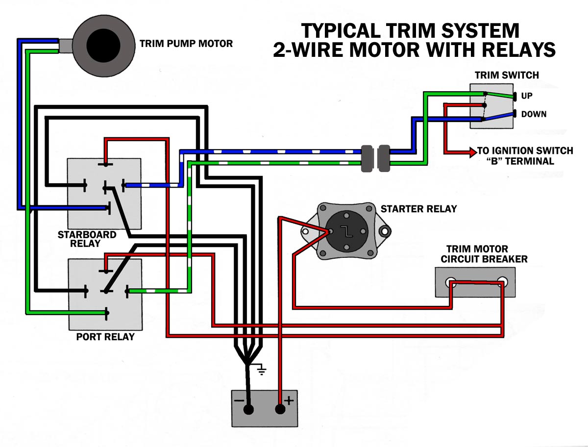
Diagram Tilt Trim Gauge Wiring Diagram Full Version Hd
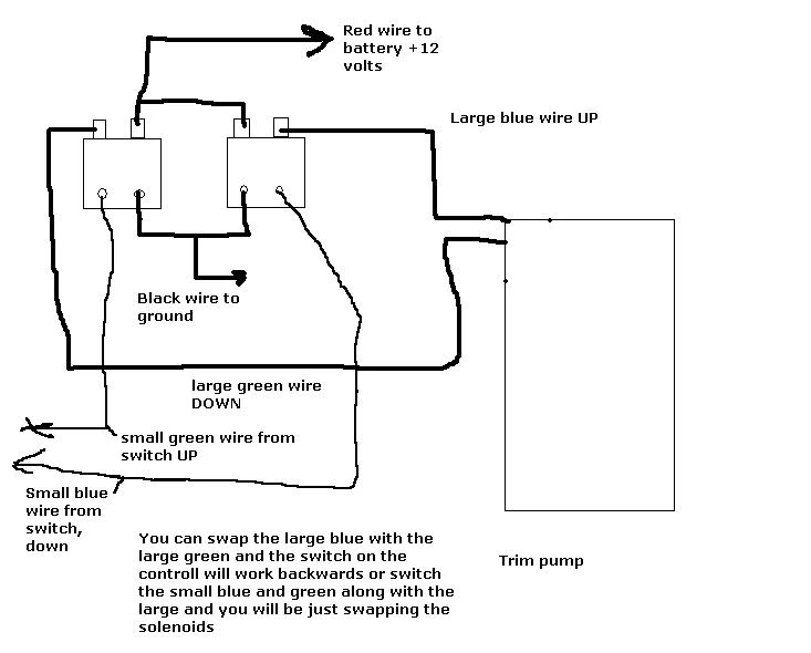
Diagram Boat Trim Wiring Diagram Full Version Hd Quality

Zy 5595 Mercruiser Gauges Wiring Schematic Wiring
Diagram Mercruiser Trim Gauge Wiring Diagram Full Version Hd
Trim Sender Smartcraft Offshoreonly Com

Diagram Mercruiser Trim Sender Wiring Diagram Full Version

Diagram 1989 35mercruiser Engine Wiring Diagram Full Version
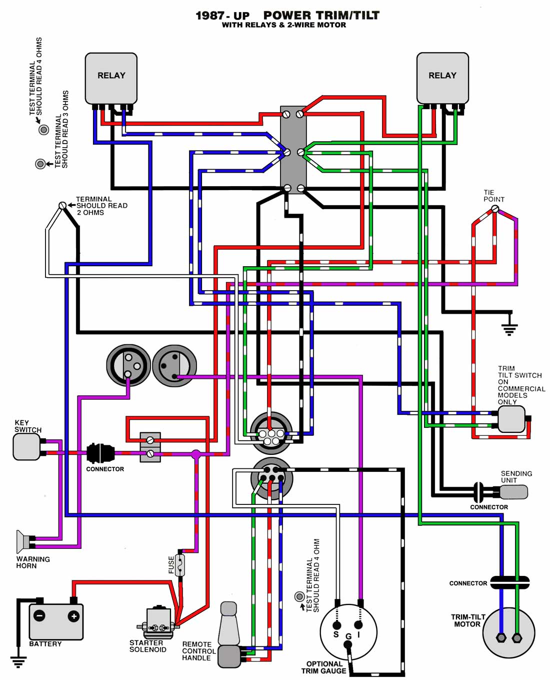
Diagram Evinrude Trim Wiring Diagram Full Version Hd Quality

Diagram 2 Wire Power Trim Wiring Diagram Full Version Hd
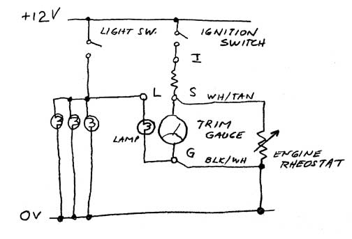
Diagram Mercruiser Trim Gauge Wiring Diagram Full Version Hd
Mercruiser Trim Sender Limit Wiring Help

Trim Sender Wiring Diagram Box Wiring Diagram

Quicksilver Stern Drive Power Trim Sender 805320a03 For Mercruiser Mc I R Mr Alpha One Alpha One Gen Ii And Bravo Stern Drives

Mn 2203 Trim Limit Switch Wiring Diagram Download Diagram
Diagram Yamaha Outboard Tilt Trim Gauge Wiring Diagram Full

Diagram Vintage Mercruiser Trim Gauge Wiring Diagram Full
Mercruiser Smart Craft Trim Sender Unit Analog To Digital
