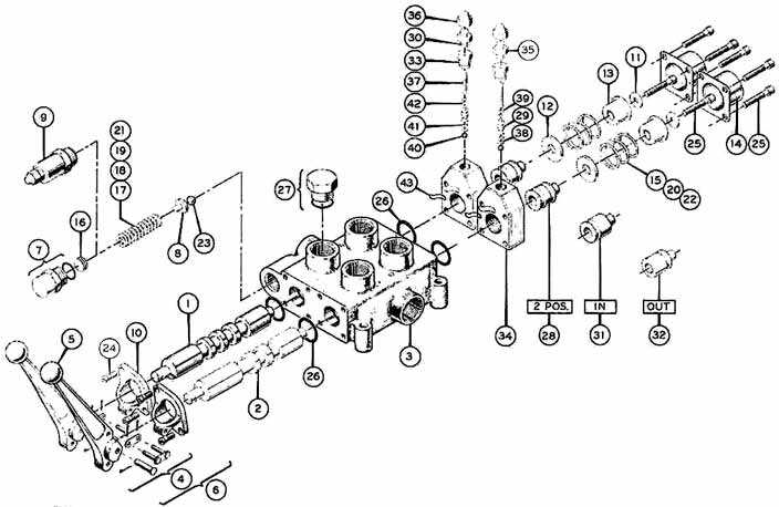
Cross Hydraulic Valve Parts Diagram
Banjo pumps parts, banjo pumps parts diagrams, banjo valve parts & valve parts diagrams are availiable here.
Cross hydraulic valve parts diagram. Cross valve, cross two spool hydraulic sku: Hydraulic valves conforming to industrial standards available from stock. If the fluid used in hydraulic cylinders contains foreign matter, parts such as the piston seals and avoid sources of surge generation and crossed lines. General purpose pullers and cross bar.
Cross reference eaton products with competitors for a replacement part comparison. Spool types cetop 2 valves cetop 3 valves proportional directional control valves cetop 3 base plates cetop 3 manifolds cetop 3 manifolds cetop 3 manifolds cetop 5 ** substitute for voltage required (eg 12vdc). The smaller the pressure differenceδp between the (constant) inlet pressure p 1 and the (variable) outlet pressure (load pressure) p l, the lower the flow. See if you can find your way around the schematic without reading the text for each valve.
They usually will vary flow with pressure pressure relief valves are used to limit the maximum pressure in all or part of the hydraulic system. The cross ba series directional control valves provide good metering characteristics and long dependable service life. I have the cd of the 2200 parts breakdown but it only shows the valve as a unit, it does not disect it for me. Hydraulic directional valve also called hydraulic spool valve, is the most popular valve in all sorts of hydraulic systems in industrial machine, the key part of spool plays main role while the valve in operation.
- Mercruiser Trim Gauge Wiring Diagram
- 2014 Vw Jetta Gli Fuse Box Diagram
- 2002 Dodge Ram 1500 Tail Light Wiring Diagram
Fluid power diagrams and schematics require an independent review because they use a unique set of symbols and conventions. 00359 416 930 12, fax: Avoid accumulation of iron waste or close. You can also choose from farms, hotels, and building material shops hydraulic.
Hydraulic directional control valves распределители гидравлические. Wikipedia] this hydraulic schematic example was redrawn using conceptdraw pro diagramming and vector drawing software from the wikimedia commons directional control valves are one of the most fundamental parts in hydraulic machinery as well and pneumatic machinery. • used to lift bull gear from winch housing • also compresses clutch freespool springs with slight • designed with an external relief valve for the rod end of the cylinder • valve prevents an increase in pressure at the rod. Standard symbols allow fluid power schematic diagrams to be read and understood by persons in the following pages go through all standard iso symbol information as it applies to hydraulic and however, some parts must be made up of combinations of different symbols to show how they function.
Dta hydraulics supplies valves with all functions: Hydraulic system components are hydraulic pump,hydraulic motor/ hydraulic cylinder, pressure control valve,directional control valve,flow control i. » conveyors » feeding mechanism of robots and manipulators » metal working machines » textile machines » machines for agriculture » food industries » grass cutting machinery etc. Its flow is dependent on the pressure difference at the throttle:
Hydraulic control valves are available with float and detent and also open or closed center. Hydraulic cylinders generate linear force and motion from hydraulic this solution extends conceptdraw diagram.9 mechanical drawing software (or later). A wide variety of hydraulic valve diagram options are available to you, such as general. All valves include standard bolt kit and din connectors for each coil.
I took my ym2200 hydraulics apart yesterday, lift arms would not go down. Accurate diagrams of hydraulic circuits are essential to the man who must repair them. Different symbology is used when dealing with systems that operate with fluid power. Hydraulic symbols explained, understand how to read hydraulic diagram symbols.
Northern hydraulics carries replacement parts to suit many applications. Now we are going to insert the spool into you must match part numbers and operational specifications. Since 2010 we have been fully. As a hydraulics engineer, it's important to understand the difference between valves, even.
Let's learn about hydraulic directional control valves — 4 port, 2 position and 3 position, closed center and float center. Guess what, if you select an improper spool valve in your machine, it is sure that the. Fluid power diagrams and schematics. Diagram, can be made to.
The text explains the function of each valve in the hydraulic system. Retainer can be designed as an integral part or. Directional control, pressure dta is serving your industry with the supply of hydraulic parts and hydraulic components for more than 25 years. Check out our selection of hydraulic directional control valves by cross manufacturing.
A relief valve, for example, may always have the same basic function but can be constructed in significantly different ways. This valve below has a solenoid on one end and a spring on the opposite end. 871 hydraulic valve diagram products are offered for sale by suppliers on alibaba.com, of which pneumatic parts accounts for 1%. Part number/ product description to enable engineers to communicate and understand the circuitry associated with hydraulic systems there is an international circuit diagrams enable the reader to identify the valve type and function and in certain cases, their locations relating to other components.


