Miller 14 Pin Foot Pedal Wiring Diagram
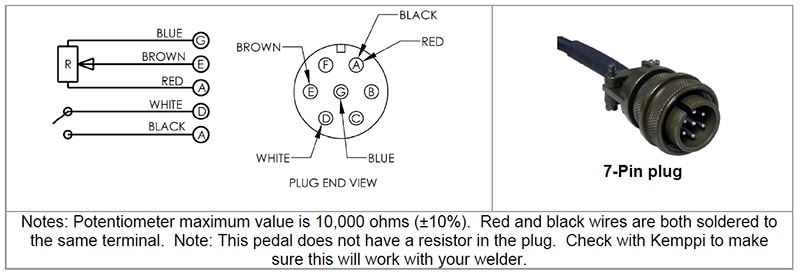
Details About Ssc Remote Foot Pedal For Kemppi Tig Welders 7pin Plug R11f

Diagram Lincoln Welder Remote Wiring Diagram Full Version Hd
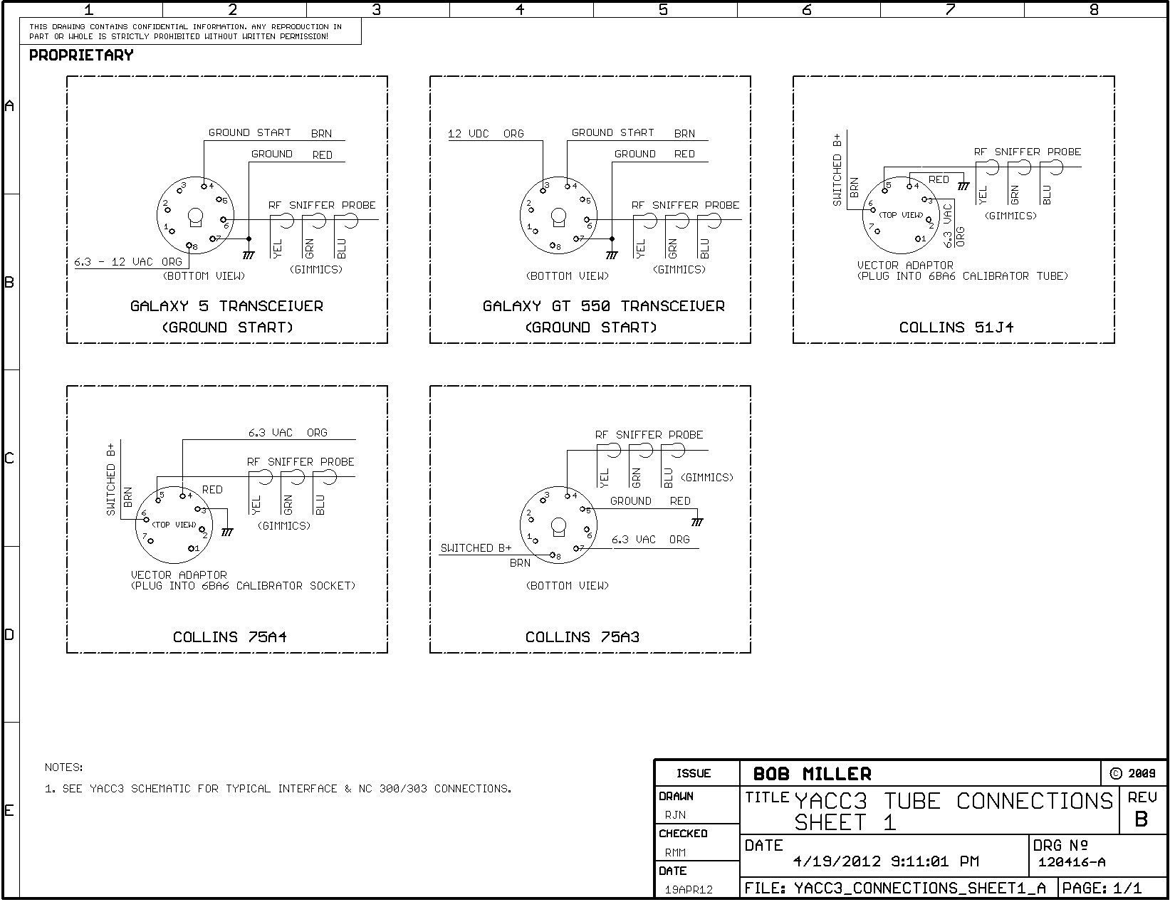
Diagram Miller 14 Pin Wiring Diagram Full Version Hd Quality
The original connectors for the flat mylar were removed with solderwick, and wires attached to the appropriate pins (which were determined by a.
Miller 14 pin foot pedal wiring diagram. Wireless foot control 300429 improves productivity and maneuverability by eliminating cord tangles. Miller tig 14pin control pinout miller welding discussion. I can rest my foot on the pedal rather than the ground. This foot pedal is used in the tig welder to control its starting current and output current.
If you have both a foot pedal and a thumb control and neither is working, the problem could be in the 14 pin remote connector on the welder. Made in usa by ssc controls company. Bosch relay wiring diagram awesome wonderful miller 14 pin wiring. Curtis model fp foot pedals are designed and manufactured to the exacting requirements of ts16949 to achieve unprecedented reliability.
I think you know this. The heel stop on this pedal is nice for long welds. The foot pedal is used to operate the motor, and. Miller wireless foot control overview:
- Husqvarna Mower Deck Belt Diagram
- John Deere D130 Deck Belt Diagram
- Dometic 9100 Awning Parts Diagram
2005 ford explorer wiring diagram gallery. Thereafter the momo pedal work with both wheels. Battery box with three aa batteries. Female connector equivalent to miller® part number 136 960, and male connector equivalent to miller® part numbers 136 961 and 141 162.
Technical information kep foot pedal. Used on foot pedals, remote wire feeders, or to build an extension cord. Over the years, the colors have moved around. Extension cord adds to standard feeder cable or remote control cable to extend component further out from the welder.
The pedal with high sensitivity responses quickly, and its control performance is not affected by temperature variation. Master catalog raychem heatshrink products Cobel tig acdc 200 wiring diagram. *arc not stopping *help 10 code (foot.
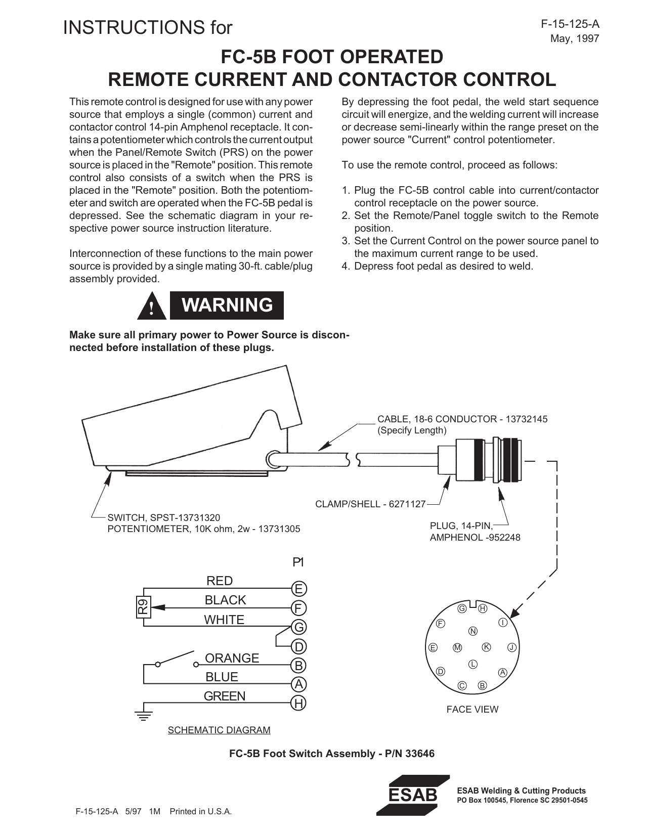
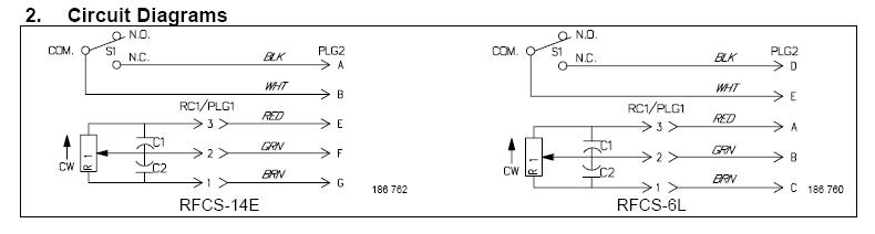
Jun 14, 2014 | miller syncrowave 250 dx tig runner welder. Foot pedal current and contactor control. Press to activate gas contactor and increase amperage; For miller® and hobart® machines with 14 pin plugs and 1k potentiometers.
Replacement parts and wiring diagram: The circuit diagram of my modification. Steve, you might want to put the everlast pin numbers rather than the wire color. Can you please tell me colors of wires that go to pins of potentiometer(dfp wheel.
Thanks andy i'll call miller about this one later on but thought some one here might know. By gschoppe in circuits electronics. Andy, most foot pedals only use 5 wires, if you take yours apart, i'm sure only 5 are used out of the 14 pins, the ohm value of the [pot] is the only. Thermal overload protection shuts down the power source output if the main transformer or rectifier overheats.
Does anyone have the wiring diagram for the foot throttle pedal? Details about tig foot pedal control on off adjustable current control 5 7 pin machines. As the stroke increases, the output current increases. Symptoms that this fix may cure:
The everlast foot pedal just didn't work for me so i called ssc controls and they made me a lincoln style pedal. Sorry for my horrible english if you have problems to understand , please send me a pm. I'm not sure if this may fix other models.
Gallery of Miller 14 Pin Foot Pedal Wiring Diagram
Wiring Pioneer 14 Pin Harness Diagram Full Version Hd Quality

Diagram Kawasaki 185 Wiring Diagram Schematic Full Version
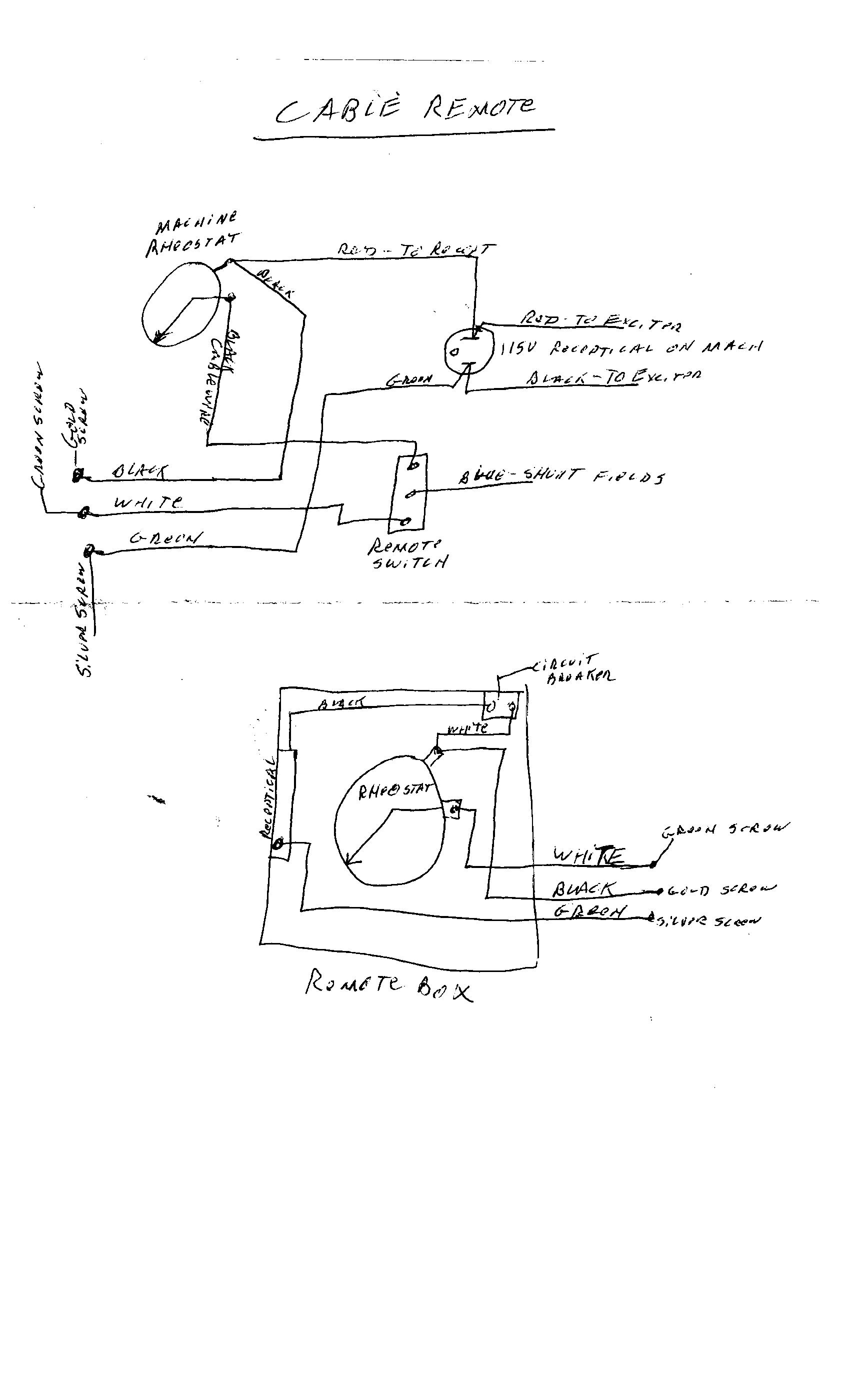
Diagram Lincoln Welder Remote Wiring Diagram Full Version Hd

Diy Tig Pedal Part 2 Youtube
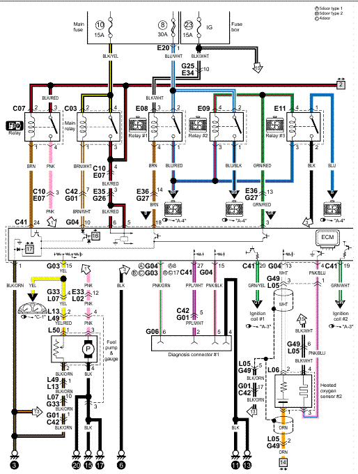
Diagram Miller Foot Pedal Wiring Diagram Full Version Hd
Warning Instructions For Fc 5b Foot Operated Manualzz
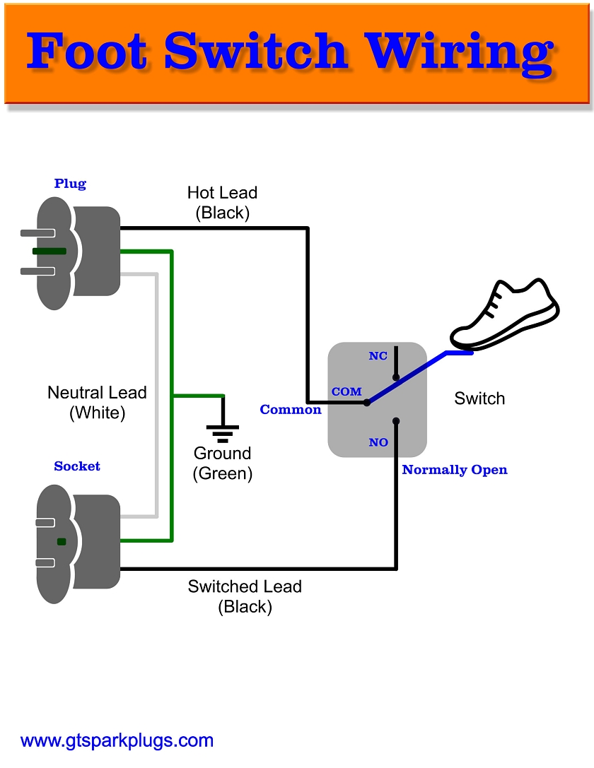
Diagram Miller Foot Pedal Wiring Diagram Full Version Hd
Older Miller Tig Pedal Conversion
Foot Control Stopped Working Miller Welding Discussion Forums
Rfc 23a Foot Pedal Miller Welding Discussion Forums

Diagram Pioneer 14 Pin Harness Diagram Full Version Hd
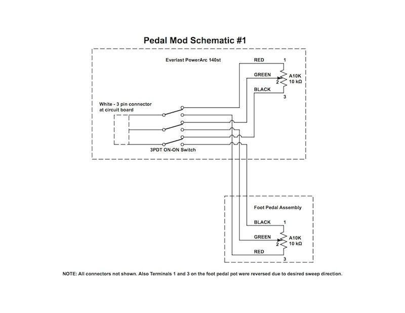
Diagram Miller Xmt 304 Wiring Diagram Full Version Hd

Diagram Miller Bobcat Welder Parts Diagram Full Version Hd
Diagram D10 Lincoln Welder Wiring Diagrams Full Version Hd
Diagram Pioneer 14 Pin Harness Diagram Full Version Hd
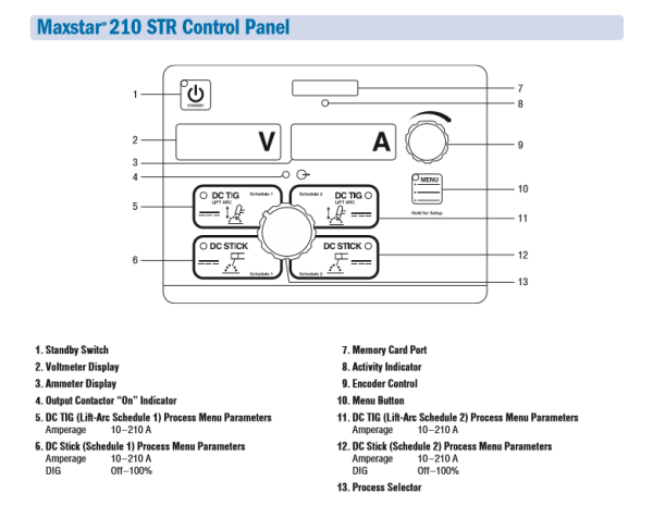
Maxstar Str 210 120 480 V 907682
Rfc 23a Foot Pedal Miller Welding Discussion Forums
