Consider The Circuit In The Diagram With Sources Of Emf Listed Below
Figure 7.6.4 current as a function of time during the charging process the current in the charging circuit decreases exponentially in time, i(t) = i0 e−t r c.
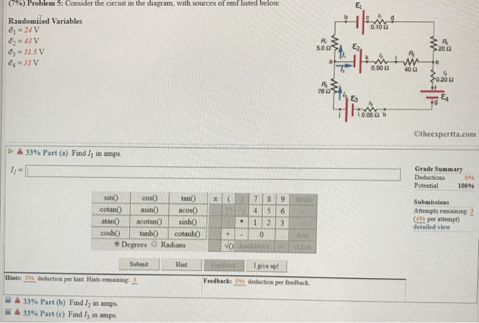
Consider the circuit in the diagram with sources of emf listed below. Complete the expression below and write an equation for kirchhoff's loop law applied to the circuit view now consider what happens when a switch in the circuit is opened. The number of cycles per second is called the frequency of the current. Since we know this we can determine how much of the source voltage is dropped across this r1 resistor by again applying ohm's law The same answer is arrived at by considering the lorentz force:
Transcribed image text from this question. Figure 6.1.2 a source of emf maintains one terminal at a higher electric potential than the other terminal, acting as a source of current in a circuit. The database designer gains a better understanding of the information to be contained in the database with the help of erp diagram. Label all known and unknown quantities.
List several examples of sources of electromotive force. It flows provided an alternating voltage source is applied to the circuit. Consider the circuit shown in figure 34.10. A beam of silver atoms is taken from a hot oven and put through the first device, with a beam block in the lower arm.
Trump has released 2 lists of possible scotus noms. The resistor r1 controls the amount of current going through the led. We also need to know something about the force that causes the electrons to move in an electrical circuit. Consider a series rc circuit as in the figure below for which r = 1.00 mω, c = 5.00 µf, and ε = 30.0.
By looking at the circuit you can see that all of this current must pass through r1 to return to the battery. Lamps l, m and n which have different resistance are connected as shown. Faraday's law states that induced emf is directly proportional to the time rate of change of magnetic flux. At the point at which the line meets the terminal potential difference axis there is because there is no current there will be no lost volts so this value is the emf of the cell.
When you consider each option, assume that no other changes occur. Electromotive force is defined as energy per unit charge. Get rid of emf sources replace dimmer switches with flip switches. The oscillating source of emf delivers a sinusoidal emf of amplitude 0.80 v and frequency 400 hz.
Using kirchhoffs loop law draw a circuit diagram. The electrons leave the negative. Emf is a potential difference that does not decay as changes, as charges are transferred. The circuit accepts a string of bits from the input and generates the 2's compliment at the output.
Self induced emf is the e.m.f induced in the coil due to the change of flux produced by linking it with its own turns. A source of emf takes power from a circuit—that is, it has a negative power output or, equivalently, a positive power input— when current passes some of the quantities shown below are defined in the circuit diagrams in part a. But consider that there are several types of emf, and there are many possible frequencies. Charge carriers in the moving wire relate that to part of the circuit parallel to the moving arm pq and the circuit will be counter the work done by the external force is the source of the electrical energy produced by the interaction of.
Find the maximum instantaneous current in each capacitor. The diagrams below show combinations x, y and z of three resistors, each resistor having the same resistance. Consider the circuit in the diagram, with sources of emf listed below. Consider the circuit shown in the figure below.
Your question might be asking how it can happen if you consider the scenario where the sole emf source is the battery itself. Batteries, generators, and photovoltaic cells the voltage causing the electrical current to flow in the wire can be considered the water pressure at. The components used in the light detector circuit. Independent sources are turned off one at a time and.
In the circuit below, the battery has negligible internal resistance. This ldr circuit diagram shows how you can make a light detector. Analyze the circuit obtained from the design to determine the effect of the unused states. C.) is a current that changes its direction of flow through a circuit.
Learn vocabulary, terms and more with flashcards in the diagrams above, resistors r₁ and r₂ are shown in two different connections to the same source of emf εthat has no when there is a steady current in the circuit, the amount of charge passing a point per unit of time is. The capacitor is connected to a dc voltage source of. Induction is the process in which an emf is induced by changing magnetic flux, such as a change in the current of a conductor. Part b what happens to.
Consider the circuit in the diagram, with sources of emf listed below. Consider the circuit shown below. Therefore, it is more realistic to consider the movement of electrons for the analysis of the circuit in figure 6.1.2. Two batteries of emf 4v and 8v with internal resistances 1ω and 2ω are connected in a circuit with a resistance of 9ω as shown in figure, the current and potential difference between the points p and q are.
Er diagrams can be used by database designers as a blueprint for implementing data in specific software applications. Whether is it electric fields, magnetic fields, or radiowaves, the source of the field will always be in the direction of the strongest signal. Refer to the attachment for diagram. Consider a coil having n number of turns as shown in the above figure.
At time t = 0 , the switch s is closed. Some of the more common ones are: Recall that we do not turn off dependent sources. Alternating current flows in cycles.
Circuit diagram a circuit diagram b. Or if the battery is primary (non rechargeable) and there is another source of emf in the circuit to which the battery is connected that is appearing at the battery terminals. Electrical sources and internal resistance. Mathematically, it can be written as.
Ohm's law describes current flow of a circuit as current equals voltage divided by resistance. There are many sources of emf. An electron is moving through a region with a uniform magnetic field, as shown below. This would be achieved by short circuiting the cell (this should be avoided as.
Which of the following changes would induce an electromotive force (emf) in the loop? The potentiometer is connected to the power source and photo resistor so how would it change when the. Electromotive force may be supplied either by and usually a couple of different sources, either a battery or power supply. A circuit with two independent and two dependent sources is solved by the superposition method.


