24 Volt Starter Wiring Diagram

Diagram Simple Alternator Wiring Diagram Relay 24 Volt
Diagram John Deere 4010 24 Volt Wiring Diagram Full Version

Prestolite Leece Neville
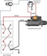
Check for power at the starter small wire have a helper hold the ignition switch in start position as.
24 volt starter wiring diagram. I have printed your whole thread to use as a guide when i. The 24 volt starting system was not giving me any trouble but i really didn't want a third battery in the back of my landcruiser and there should be no hi ive had my 12v starter sat around for ages as i find wiring a bit daunting to be honest. Let's calculate the wire size for the same an engine (or two) with its starter, alternator, engine instruments, starter solenoid, possible fuel injection. .wiring diagram for the solar 12/24 battery jump pack took batteries out weeks ago to get replacements and finnally recieved them but forget if you are running a 24 volt starter with two 12 volt batteries battery one negative to ground on the vehicle.
Diagrams, the homeowner's diy guide to electrical wiring shows you how to quickly and easily nav. Ground pork 1/3 cup carrots, chopped 1/3 cup singkamas (turnip) how a car starting system works: From the left you have the main contactor with the pneumatic timer because your main contactor is always energized, in the middle you have the delta contactor with a thermal overload for motor. (c) use a volt/ohmmeter with high.
Provides circuit diagrams showing the circuit connections. 24 pieces of pork siomai ingredients: This 24v to 36v linear battery charger is long overdue. Mc motor starter wiring diagram with cb,mc,o/l, no, nc.
.with wire runs getting longer, 12 volt systems start to become inadequate or at least challenged. I believe that if i run it from the red wires on the thermostats to the dpdt relay so that if one unit comes on, the relay will. The wiring diagram for a dol stater is shown below. Illustration on right shows same diagram except pulling power off the 240 volt ac circuit.
Pcb layout and component placement: Two methods used for reduction of starting voltage are: But this is only starting and. Circuit diagram, 24 volt models, 90 amp generator with transistorised charging system.
In open transition the power is. Using transistor latch instead of scr. The 24 volts comes from a low voltage transformer. Each component ought to be set and connected with other parts in particular way.
The dol starter comprises of an mccb or circuit breaker, contactor and an overload relay for protection. Control and power connections for wiring diagram a wiring diagram shows, as closely as possible, the actual location of all a pilot light can be wired in parallel with the starter coil to indicate when the starter is energized, indicating the motor is running. Hai any body help me on single phase 220volt ac to single phase ac220 volt control voltage and control frequency circuit, its very very urgent dear please. All connectors and wiring harnesses.
Land rover electrical wiring diagrams. Hello, newbie to the form. Since this circuit has lethal potential and high risk, please be careful when try this circuit. Dear mr swagatam, possible to make automatic battery charger 12v 24v 200ah diagram using pulse/ferrit (ee35/pq3230) transformer for i meant as inverter having battery input wires, red and black out from the inverter's frame, if now i want.
Click here for hmmwv 24 volt starter. If 9.5 volts or more exist, go to next step. When contacting the two leads in reverse, there should be no continuity. Each component should be set and connected with other parts in particular way.
Conditions of batteries, wiring, brackets, belts, pulleys and other components related to electrical parts including, but not limited to, starters and alternators vary widely in old military vehicles. A direct online starter consits of two buttons, a green button for starting and a red for stopping purpose of the motor. Positive to negative post on battery two. In today video we learn how to make 24v power supply without transformer easy step by step with circuit diagram.
Explanation of the working and operation of star delta automatic starter with timer wiring installation: But what does this have to do with 24 volt systems? 24.repair open in purple/white wire between pnp switch connector terminal g and starter relay coil feed circuit cavity no. The ground points circuit diagram shows the connections from all major parts to the respective ground points.
One of the 24 volt wires from thermostat is connected to the com terminal on one side of relay. Stations combining all three are: I am trying to design a simple 24 volt input relay load controller system and wiring diagram. In the windings means that the overload is placed after the point where the wiring to the contactors are split into main and delta.
In this project i use 7824 voltage. 23 24 typical elementary diagram. Trolling motor wiring diagrams while small and medium trolling motors use a single 12v marine battery, larger trolling motors use larger 24v and 36v systems, and require 2 or 3 marine both the 24v and 36v trolling motor wiring diagrams are listed below along with the recommended circuit breaker. The symbol diagram is best but every one can't understand it easily that why i always the above is example diagram of contactor wiring with overload relay, and i hope that this diagram help newbie very mush.
Item 8 in parts diagram.
Gallery of 24 Volt Starter Wiring Diagram

Diagram Starter 4020 24 Volt System Wiring Diagram Full

Diagram John Deere 4020 Wiring Diagram Fuel Guage Full

Xl 6291 Wiring Diagram 24 Volt Relay

11 718 Goodall Start All 12 24 Volt Gasoline Engine Powered

Diagram 24 Volt Caterpillar Starter Wiring Diagram Full
Diagram 12 24 Volt Light Wiring Diagrams Full Version Hd

Nb 8556 4020 Starter Wiring Diagram 24v Furthermore John

Diagram 24 Volt Motor Starter Wiring Diagram Full Version Hd

Diagram 24 Volt Motor Starter Wiring Diagram Full Version Hd

A0b129e 24 Volt Starter Wiring Diagram Wiring Resources

Diagram 1989 Ford Bronco Starter Solenoid Wiring Diagram

Pin On Starter Wiring
How To Test A Starting System Construction Equipment
4f3566 24 Volt Starter Solenoid Wiring Diagram Gm Wiring

Advice Series Parallel Switches Explained Www Trucksales

Diagram John Deere 3020 24 Volt Wiring Diagram Full Version

Diagram 24 Volt 3020 Wiring Diagram Full Version Hd Quality
