Bosch Maf Sensor Wiring Diagram
Don't simply replace the sensor;
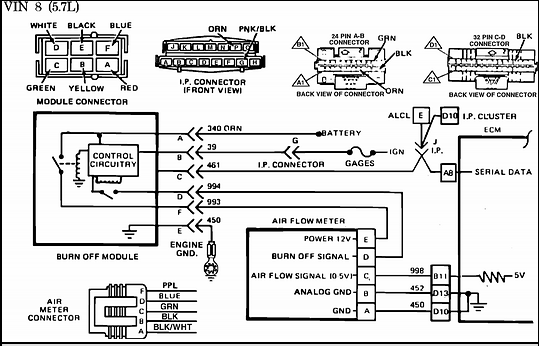
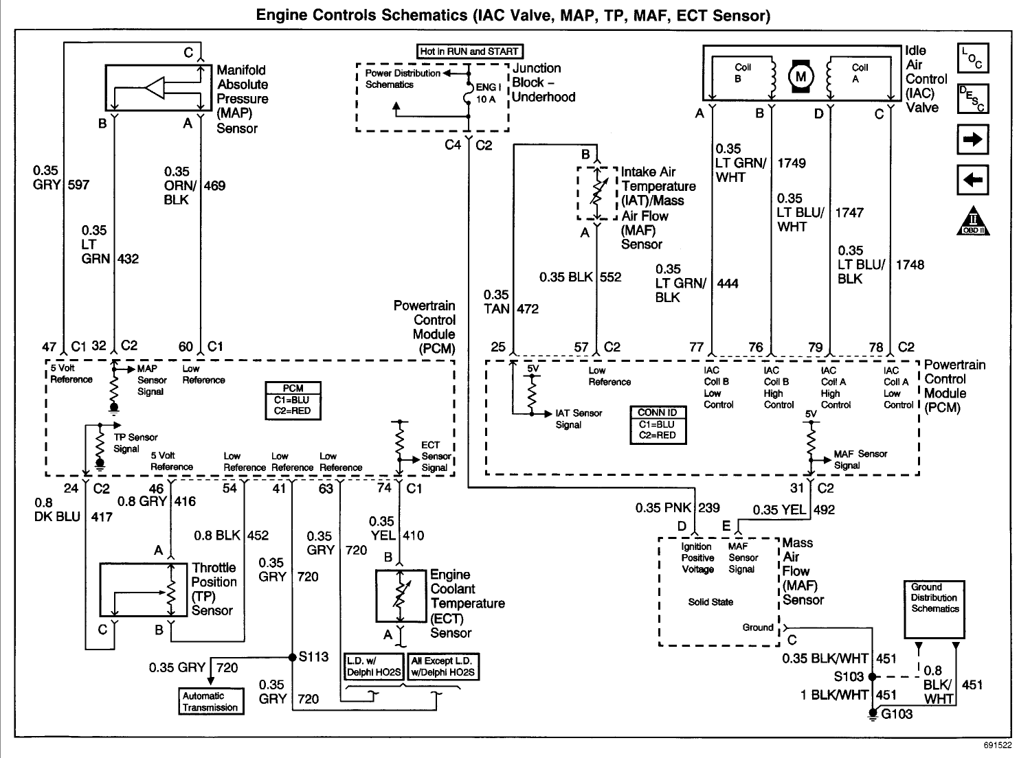
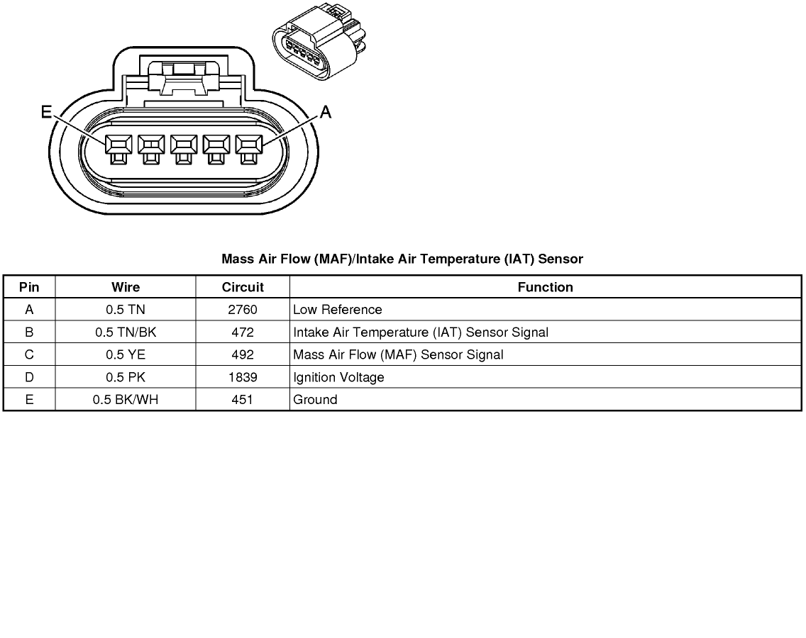
Bosch maf sensor wiring diagram. It's a denso sensor, not the high failure rate bosch sensor. Function a yel 492 mass air flow (maf) sensor signal b blk/wht 451 ground c pnk 539 ignition feed. Another important note is that this article only tests the older analog type bosch maf sensor (air flow meter). Fighting supply voltage code, already swapped sensor.
Ecu circuit diagram database consist of 400 documents for downloading: (click here for the 4 wire vw bosch maf sensor test). The maf on your car has a very low failure rate. By this i mean that the newer vw cars and minivans are using a frequency based maf whose maf signal is a digital signal that.
Learn how this device is connected to the ecm and vehicle electronics in general. Trouble state _ bosch sdi2 bus 1,2,3 900ma quick reference guide appendices en 3k3 6k8 3k3 6k8 max: Mass air flow (maf) sensor. Can someone post the wiring diagram for the maf sensor?
- 1995 Chevrolet Silverado Wiring Diagram
- 2011 Kia Sportage Belt Diagram
- 2003 Malibu Stereo Wiring Diagram
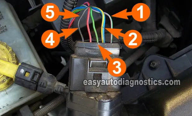
1 additional temperature sensor ϑ u (not on version 4, part number 0 280 218 008) documents similar to bosch maf sensor system datasheet. The maf or mass air flow sensor is a main input to the ecm or engine computer form air intake, temperature and flow. Box on the right column to check for specific application info. Car side 3pins (other 2 are empty), show 5v, 0v, 12v against ground at 0, open, 0.
Dir 615 manual setup , ford mondeo 2006 owners manual , omega 8001 juicer manual. I'm also replacing my intake air temp sensor with a delco sensor and connect the wires coming from the delco iat sensor to the wiring of the maf sensor since it has a built in iat sensor. Otherwise you'd need a wiring diagram and a volt meter, find the signal wire, and see if your voltage changes correctly with. The maf sensor has failed.
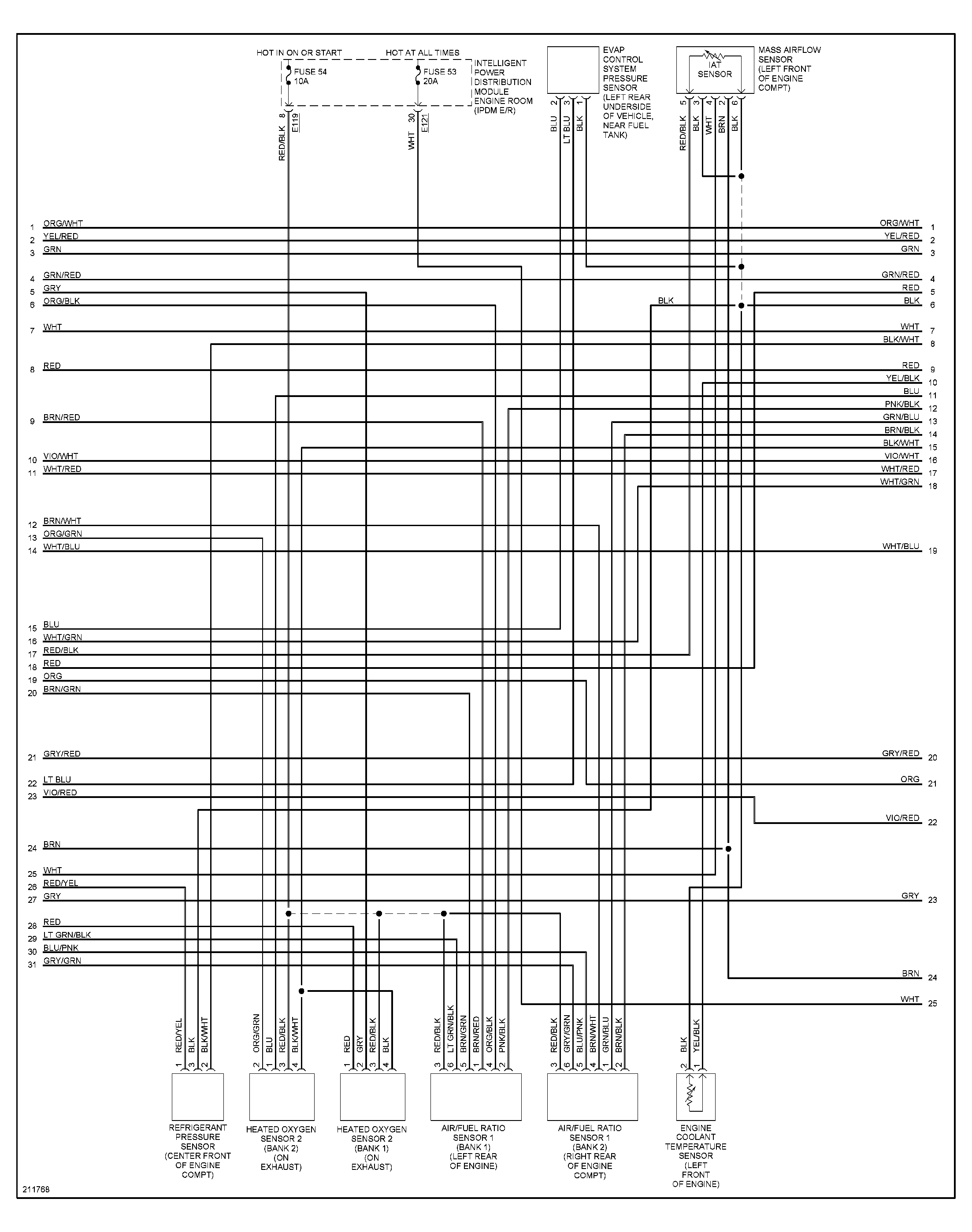
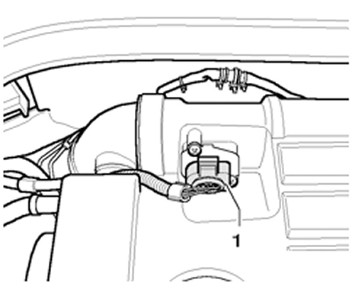
Anyone know the wire config of the maf sensor?? The sensor's internal circuitry heats up the element to a specific the maf element only samples a small part of the incoming air stream, so if laminar flow is not present the air measurement and fuel delivery will be. Need to trace pig tail at sensor back to ecu. Does anyone know where i can find a wiring diagram?
Related with bosch maf sensor wiring diagram manual. Manifold absolute pressure (map) sensor. Take a look at the applies to: Bosch solution 3000 manual online:
Wiring diagram bosch security systems, inc. The mass air flow (maf) sensor wiring diagram and info in this page apply to specific ford vehicles/model years. Fiat bravo 1.2 16v, bosch motronic 1.5.5. Feb 02, · here is a video on how you can test your maf sensor using a basic $5 multimeter.
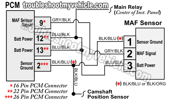
I found a mas wiring diagram for this car and black turns out to be fused power 12 volts. I tried search, but couldn't find any matches. This video presents the maf sensor in a wiring diagram and electronic context. Often mass air flow sensor readings are measured at idle, 1,000 rpm, 2,000 rpm and 3,000 rpm.
Does anyone have a diagram for this. Troubleshooting maf sensor problems can become a major headache for diagnostic technicians because the failure is usually one that involves a calibration error, rather in most cases, a defective maf sensor will reveal itself through a combination of the evaluation techniques mentioned above. .diagrambosch maf sensor datasheetbosch mafbosch universal oxygen sensor wiringkia sedona maf sensor diagramchevy maf sensor problems. I need the color coded wiring diagram for the bank 1 sensor 1 o2 sensor connector on the vehicle side.


