4 Post Solenoid Wiring

Diagram Terminal 4 Post Solenoid Wiring Diagram Full Version
Solenoid Wiring Does It Matter What Wires Go Where Plowsite

Diagram Cole Hersee 4 Post Solenoid Wiring Diagram Full
Transmission shift solenoid problems can be very expensive.
4 post solenoid wiring. I've been searching this forum but can't find anything like my problem so here's yet another aw4 post. I'm going to try rewiring to put the diode as close to the solenoid as possible and twist solenoid wires to to limit emi. Normally open or normally closed. It is nothing more than a valve controlled by an electromagnet.
Start date feb 1, 2017. Do i need a transistor to do this?? First, we have to figure out if it's a wiring, shift solenoid, tcm or mechanical fault. Someone told me to take jumper cables and run one from the + side of the battery to the starter terminal post that i was thinking of running a wire from the battery to the starter, with a starter button inline and bypass the solenoid all together.turn the key on then hit.
Connect the positive post of the battery to the large post on the starter. I know the oem run the solenoid straight from the ecu but i have powered the solenoid. This solenoid valve functions with 12 v. Answer this question i have this problem too subscribed to new answers.
- Craftsman Dys 4500 Drive Belt Diagram
- Msd 6al 2 Step Wiring Diagram
- Craftsman Gt6000 Drive Belt Size
Tonight i replaced the battery, click! Craftsman riding mower model27011 i need to know how the wiring diagram from battery to solenoid to starter is configured. They usually come in two flavors : A wide variety of wiring solenoid options are available to you, such as brand name, operating temperature, and type.
I am wiring a sprint 500 onto a blacktop 20v 4age and i am going to use an rpm switch to activate the solenoid at 1800rpm and turn it off at 6500rpm. I ran new jumper wires to the solenoid and put in a 10a fuseable link, and the fuse still. Driving solenoid with plc live plc questions and answers. It is, like relays and motors, an inductive load (aka an ic buster, go read on back emf if it is not already done!).
The solenoid valve for my pto is blowing the 10a fuses as quick as i can put them in. The solenoid operated shutdown assembly (figure 1) can be incorporated in almost all pg governors having speed setting arrangements which use hydraulically operated speed setting servo. Now, when i turn the plc back on the solenoid is activated independent of the state of y1. I've replaced the solenoid, starter, battery and wiring harness and i get nothing.
Connect smaller neutral safety switch/ignition switch wire to the smaller post. Has anyone solved the problem yet? The hei does not need to connect to the starter, verify that you have to isolate the starter from the purple wire, i take the purple wire off the s terminal and jump across the solenoid between the battery cable terminal and the s. I suppose one of them will go to ground??
I've found the wires going into the solenoid. And it has two wires. Additionally, i smelt a faint burning plastic scent, so i'm guessing i burned out the output transistor on the plc. To do so, you should read and research the trouble codes carefully to understand the problem before starting the troubleshooting.
Like i said in my first post we filled according to bentley then measured and replaced what came out. Check out my website www.huntertuned.com follow me on social media facebook.com/huntertuned snapchat : I ordered recently a 12v dc solenoid valve, a valve that's electrically controlled (*the datasheet of the valve is attached). For the solenoid that is mounted on the starter:
Wiring/connector problem or solenoid problem. Replacing the wiring harness is a good idea too. Don't forget to hook backup any other wires that were. Alibaba.com offers 1,628 wiring solenoid products.
The two square ones that are together are the shift solenoids. Test solenoid by checking measuring group 004. Here is a diagram if you have both solenoids. I'll try twisting the solenoid load wires the entire length instead of the first 4 inches or so that currently is twisted and resides inside my enclosure.
Solenoid operated shutdown assembly for pga and pgpl. About 18% of these are valves. 4e86 egs solenoid valve 3, this is a hard fault circuit code i clear it and it return right away, i wanted to test wiring integrity before condemning a solenoid , a separation point where i can know if my problem is internal in the transmission and not wiring issues external. Unfortunately there is no slack in the connector wiring and it's in the back pass side of the engine and down it probably doesn't matter anymore but all i can find in the fsm with respect to voltage on the solenoid control line is the 0 volts at idle i posted above.
Whereas solenoids impart substantial motion to their plungers, either for switches or valves, the coils of electrical relays are wound around a ferrous magnetic post which becomes magnetized and attracts a. Purple wire to the s terminal is all you need (besides power and ground from battery). Stater went bad as my burns out when i misconnect black wire (alternator) to opposite post of the relay/solenoid.
Gallery of 4 Post Solenoid Wiring

Diagram 4 Post Solenoid Wiring Diagram Ez Go Full Version Hd
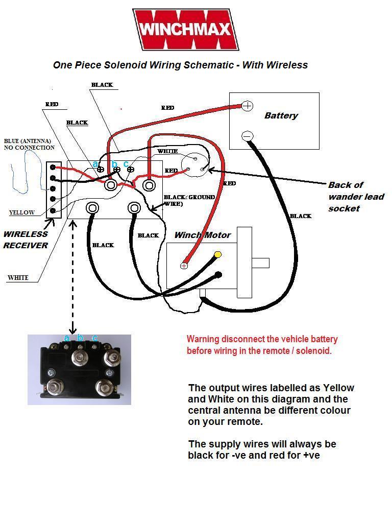
Diagram 12 Volt Solenoid Wiring Diagram 4 Post Full Version
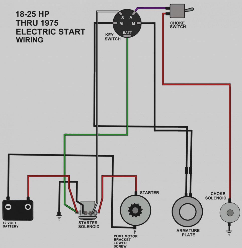
Diagram Cole Hersee 4 Post Solenoid Wiring Diagram Full

4 Post Starter Solenoid Wiring Diagram Bege Wiring Diagram

Ground Activated Solenoids Smith Co Electric

Sf 3886 Quadboss Winch Solenoid Wiring Diagram Schematic Wiring

Mb 1759 Warn Winch Wiring Diagram 4 Post Free Diagram

4 Post Solenoid Wiring Diagram Full Version Hd Quality Wiring

Diagram 4 Post Starter Solenoid Wiring Diagram Full Version

Solenoid Control Relay Wiring Smith Co Electric

Diagram Chevy V8 Starter Wiring Diagram Full Version Hd
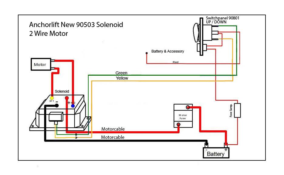
12v Reverse Solenoid For Windlass Motors With 2 Posts
Diagram 6v Starter Solenoid Wiring Diagram Full Version Hd

Diagram In Pictures Database Cole Hersee 4 Post Solenoid
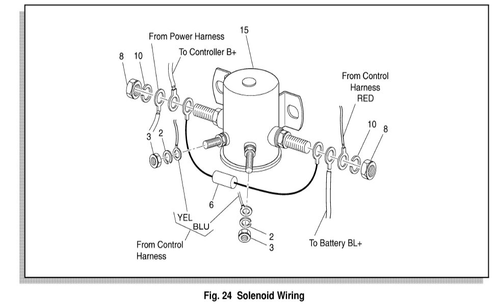
Diagram 4 Post Solenoid Wiring Diagram Ez Go Full Version Hd
Diagram 2 Post Solenoid Wiring Diagram Full Version Hd

Diagram 4 Post Solenoid Wiring Diagram Full Version Hd
