4 Post Solenoid Wiring Diagram

Diagram 5 Post Solenoid Wiring Diagram Full Version Hd
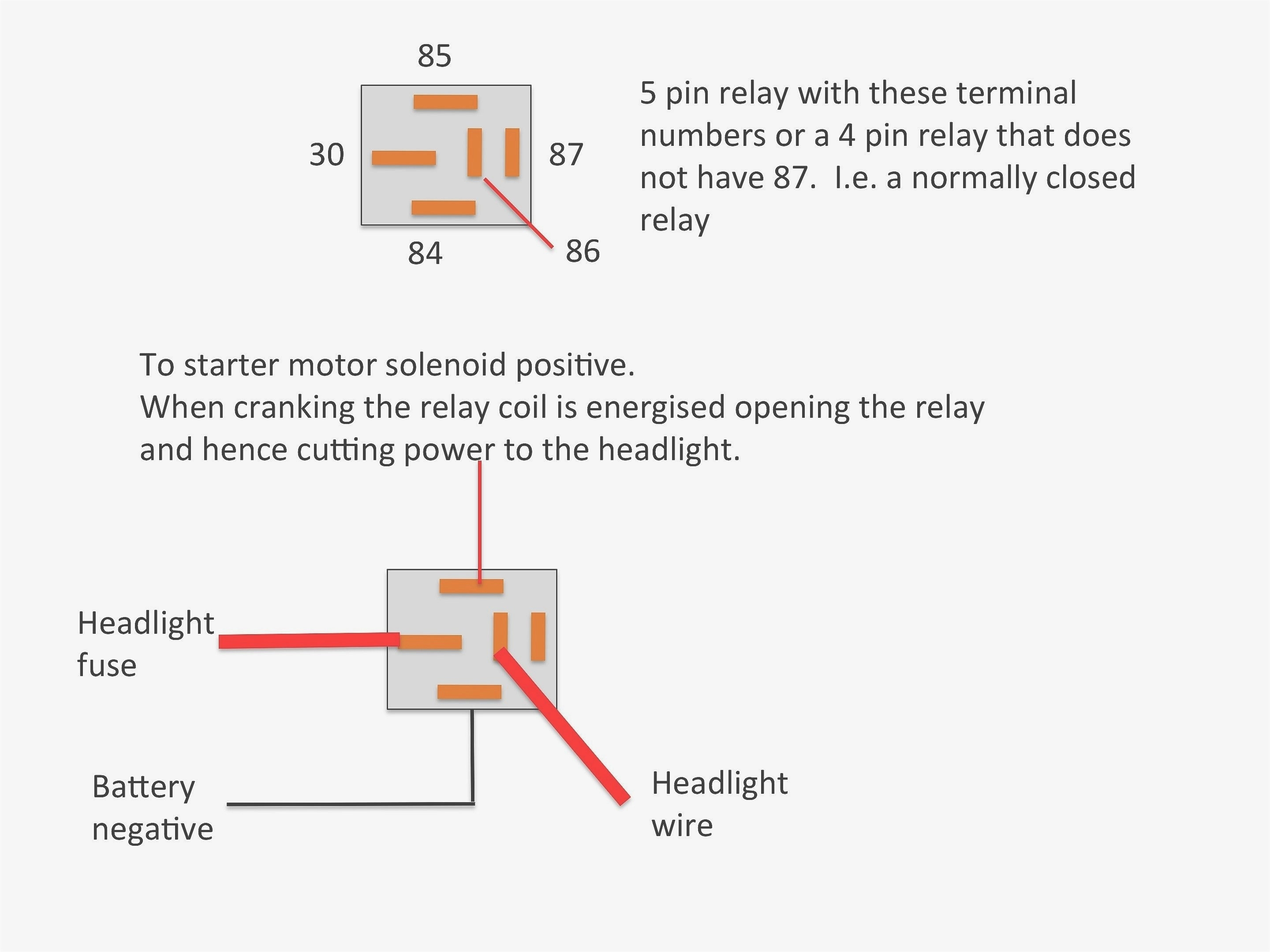
Diagram 4 Post Starter Solenoid Wiring Diagram Free Picture

Diagram 4 Post Starter Solenoid Wiring Diagram Free Picture
That solenoid has an inrush current draw of 4.4 amps and a holding draw of.38 amps.
4 post solenoid wiring diagram. Can you please show a circuit diagram how everything is connected to each other. Purple wire goes to the solenoid on starter.if you installed starter with single wire post all you have to do is mount a solenoid to the frame just in front connect smaller neutral safety switch/ignition switch wire to the smaller post. Mv = coil of solenoid. Sheet 3 centre console and electrically.
This energizes the solenoid and mechanically blocks the shift lever from going into the reverse position. And heres the wiring diagram: Your wiring diagram shows that the relay coil is being powered directly from an output pin. I've been searching this forum but can't find anything like my problem so here's yet another aw4 post.
Transmission shift solenoid problems can be very expensive. Electronics tutorial about the linear solenoid actuator, electromagnetic linear solenoids used as actuators and their duty cycle. Kubota fuel shut off solenoid wiring diagram ~ you are welcome to our site, this is images about kubota fuel shut off solenoid wiring diagram posted by benson fannie in kubota category on nov 09, you can also find other images like wiring diagram, parts diagram, replacement parts. First, we have to figure out if it's a wiring, shift solenoid, tcm or mechanical fault.
- Radio Wiring Diagram For 2006 Chevy Silverado
- 2008 Chevy Silverado Starter Wiring Diagram
- 2002 Mustang Gt Serpentine Belt Diagram
This is the way the 98's function as well as the old lt1 stuff also. Don't forget to hook backup. Starter switch to starter solenoid to neutral start switch. To read and interpret electrical diagrams and schematics, the basic symbols and conventions used in the drawing must be understood.
The following basic wiring diagrams show how batteries, battery switches, and automatic charging relays are wired together from a simple single battery / single engine configuration to a two engine, one generator, and four battery bank system. 3) a crank shaft made from strong iron wire ( bicycle start wound copper wire along the length of pipe in uniform way i keep the length of solenoid 4.5 cm. I have attached the one i have but it does not include the glow plugs or stop solenoid and seems to be missing fuel pump wiring. 2) solenoid coil (how to make this coil i will cover in next step ).
The timer your using has a spdt switch for output. Did you remember the short jumper wire that goes from the s terminal on the oem solenoid to the batt terminal? The top countries of supplier is china, from. We will understand why it is designed so, once after taking a look at the complete circuit.
Can anyone point me to a good complete wiring diagram for this engine ? 2.3.5 wiring diagrams position indicator. The linked images are printable but may print across more than 1 page (in order to be legible). Termination block window lift relay.
Note that the external wiring diagram in this sensors and wiring section is entirely separate from, though similar to, the relay board. 2.3.4 wiring diagram radiation resistant solenoid. Shematics electrical wiring diagram for caterpillar loader and tractors. Electrical diagrams and schematics, electrical single line diagram, motor symbols, fuse symbols, circuit breaker symbols, generator symbols.
The complete circuit diagram for solenoid driver circuit is shown in the image below. Use test equipment, wiring diagrams or take the vehicle to a person that has those skills and resources. Sheet 2 additional and alternative circuits. Answer this question i have this problem too subscribed to new answers.
Craftsman riding mower model27011 i need to know how the wiring diagram from battery to solenoid to starter is configured. 401 solenoid valve wiring diagram products are offered for sale by suppliers on alibaba.com, of which valves accounts for 2%. 2020 popular 1 trends in automobiles & motorcycles, home improvement, electronic components & supplies, tools with wiring diagram and 1. To do so, you should read and research the trouble codes carefully to understand the problem before starting the troubleshooting.
The single relay controlled starter solenoid wiring diagram is as shown in the following picture. The original poster fixed his issue when he discovered he incorrectly connected wires. A wide variety of solenoid there are 29 suppliers who sells solenoid valve wiring diagram on alibaba.com, mainly located in asia. I'll try twisting the solenoid load wires the entire length instead of the first 4 inches or so that currently is twisted and resides inside my enclosure.
Here is a diagram if you have both solenoids. Note that relay board supplies 12v for the fuel pump (through a relay), it does not ground the fuel pump (db37 pin #37 grounds the relay solenoid, which switches. Purple wire to the s terminal is all you need (besides power and ground from battery).
Gallery of 4 Post Solenoid Wiring Diagram
Diagram 12 Volt Solenoid Wiring Diagram 4 Post Full Version
1101 Starter Switch Wiring Diagram For Briggs Stratton
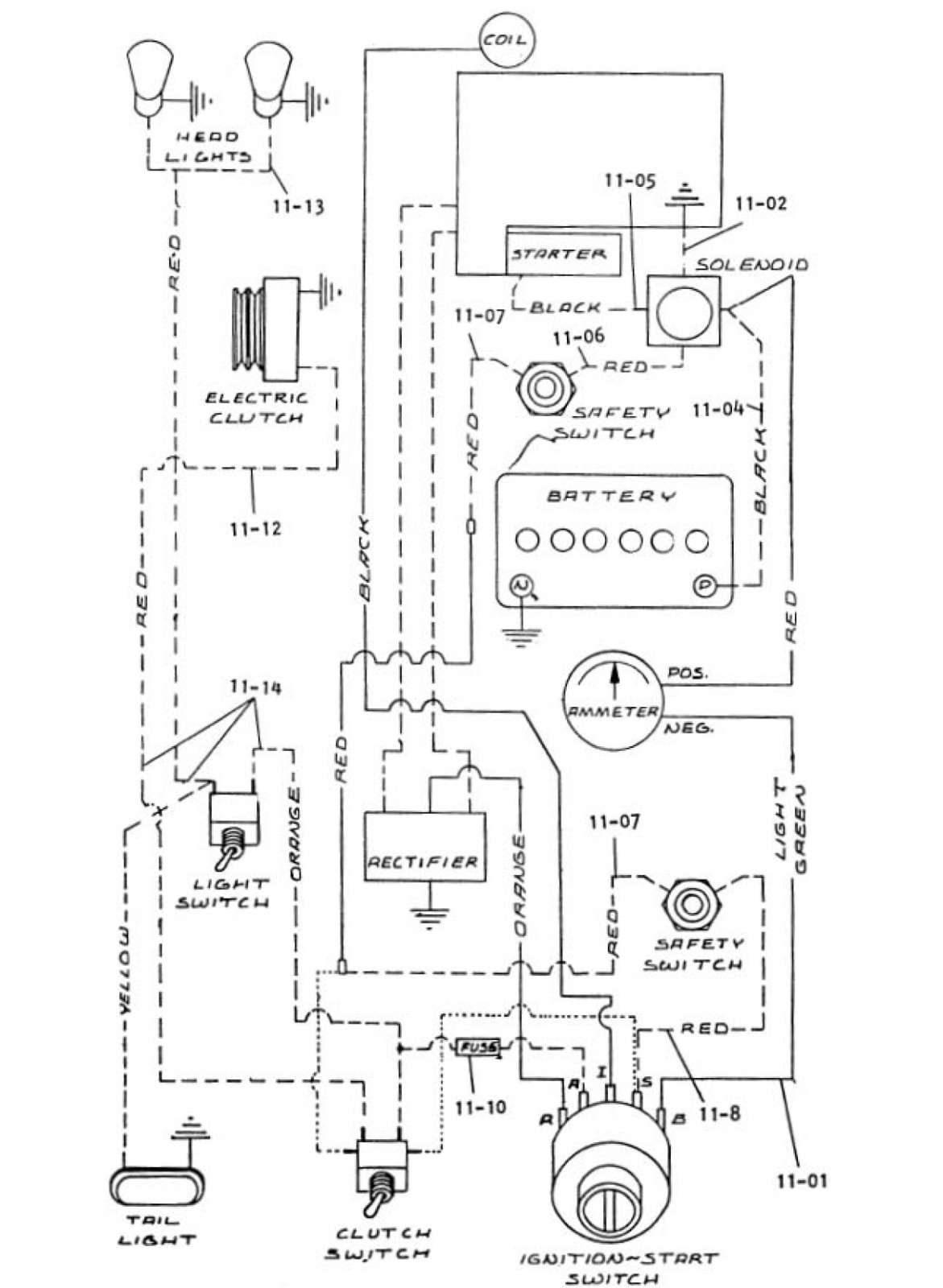
Diagram 4 Post Clutch Solenoid Wiring Diagram Full Version

Diagram 4 Post Clutch Solenoid Wiring Diagram Full Version
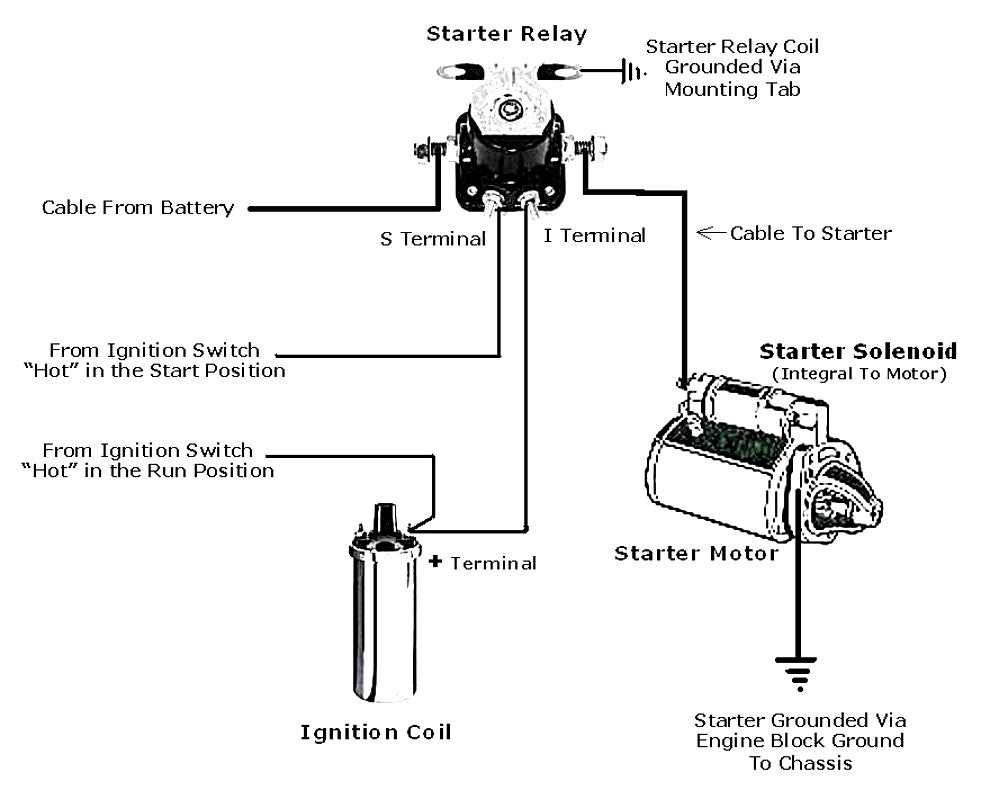
Diagram Eagle 4 Post Wiring Diagram Full Version Hd Quality

Diagram 4 Post Solenoid Diagram Full Version Hd Quality

Diagram In Pictures Database Terminal 4 Post Solenoid
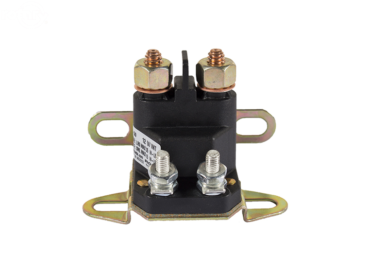
Universal Starter Solenoid 4 Pole 12 Volt
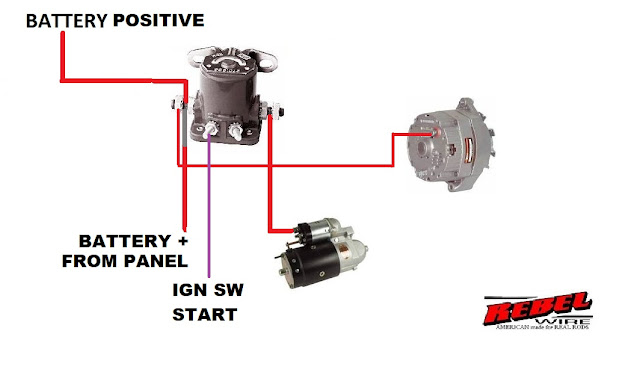
Diagram 2 Post Solenoid Wiring Diagram Full Version Hd
Diagram 2 Post Solenoid Wiring Diagram Full Version Hd
Diagram Eagle 4 Post Wiring Diagram Full Version Hd Quality
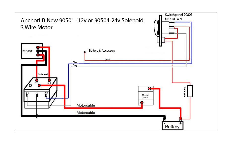
Solenoid For Windlass Motors With 3 Or 4 Posts

Diagram In Pictures Database Cole Hersee 4 Post Solenoid

Ay 2879 4 Pole Starter Solenoid Wiring Diagram Schematic Wiring

Diagram In Pictures Database 4 Post Solenoid Diagram
Diagram Cole Hersee 4 Post Solenoid Wiring Diagram Full
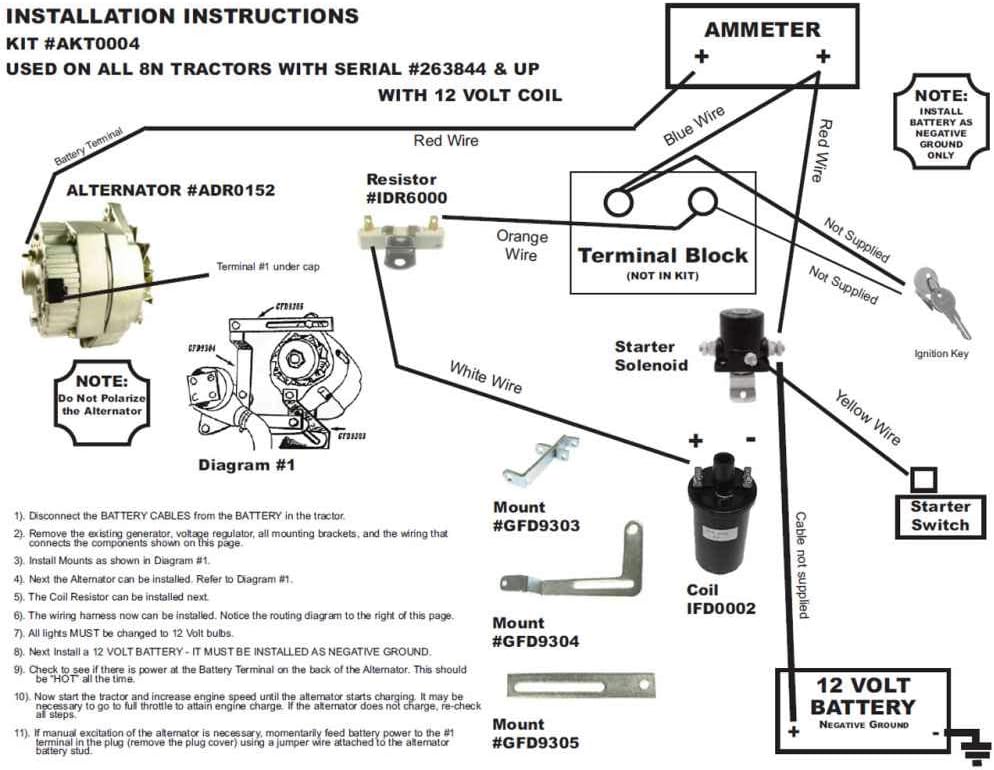
Diagram 4 Post Starter Solenoid Wiring Diagram Full Version
