Wiring Diagram Alternator Regulator
Find solutions to your alternator regulator wiring diagram question.
Wiring diagram alternator regulator. Posted by circuit diagram in automotive wiring. See the wiring diagram above (rough schematic of engine wiring) for the alternator with an internal voltage regulator. Wiring these alternators is quite easy. Xc60 2014 group 32 alternator and voltage regulator.
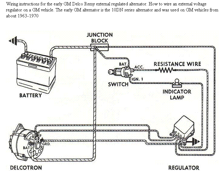
When wiring an alternator with an internal voltage regulator, remove the blue and green wires from the old external regulator under the back seat and splice them together. First the alternator/ regulator were bad, got those fixed/replaced, now its overcharging.16, 17 volts at the battery terminals and rising. Wiring instructions for the early gm delco remy external regulated alternator. Feed the alt off the.
Disconnect (cut back & tape up) all wires from the generator. Ask google for skoda wiring diagrams and various sites give info on downloading. Connect alternator to balmar regulator wiring harness as indicated in wiring diagram included on page 12. To identify an alternator system, inspect wire or wires that come from under or behind the blower housing.
This section contains how to rebuild and repair your 12v alternator (sev or motorola) and how to adjust the voltage regulator and how to check the battery. Here is the wiring diagrams for the alternator so you can see how the system works with a guide to test the wiring as well. How to wire an external voltage regulator on a gm vehicle. We shifted to my ship app please click here to download.
829 wiring diagram alternator products are offered for sale by suppliers on alibaba.com, of which car alternator accounts for 1%, diesel generators accounts for 1%. The voltage regulating system is a control chip in the voltage regulator circuitry that's inside the pcm and cannot be repaired independently, the entire pcm must be replaced. The part of an ac generator in which the voltage is produced is known as an armature. Most new alternators have internal voltage regulators, meaning wiring is not necessary, but if you have an external regulator then you need to hook it up to the alternator and ignition system.
Related searches for alternator voltage regulator circuit schema alternator and voltage regulator schematicalternator voltage regulator circuitalternator regulator circuit. Suppose the output voltage and current are increased above the normal value. .alternator voltage regulator wiring diagram.or a schematic diagram of the charging system. I would run the alt bat on your trad diagram from the alt directly to the solenoid, it needs to be 8 or 10 ga.
The car alternator has some circuitry inside it. Alternator regulators from ford should have four posts. • a single wire with no diode is generally • a single wire feeding an electronic component (regulator/ rectifier) is a rectified and regulated system which is less dependent on engine speed. A wide variety of wiring diagram alternator options are available to you, such as alternator assembly, alternator parts.
Operation principle of brushless alternator in all alternators, voltage may be generated by rotating a coil wire in the magnetic field or by rotating a magnetic field within a stationary coil wire.it doesn't matter whether the coil is moving or the magnetic. Otherwise, the structure won't function as it ought to be. This component primarily consists of coils of wire that are large enough to carry the. If a new regulator is being installed along with the alternator, complete its wiring installation according to the instructions included with your regulator.
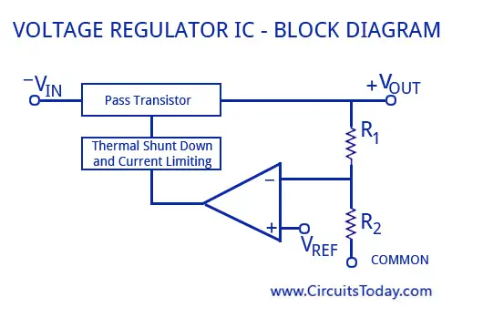
Voltage regulator circuit with schematic diagrams apr 02, 2012adjustable voltage regulator circuit using lm317. I think i may have a short somewhere or that my alternator isn't matched to my regulator/wiring properly. Checking wires using voltage drop. A voltage regulator controls the alternator voltage output to maintain a preset charging voltage for the battery.
Here is the factory wiring diagram portion: The motorcraft 3g alternator can be found from numerous sources. To eliminate this possibility you need an ign sw w/ an acc terminal. The pivot bolt, terminal end nut, voltage regulator, regulator wiring plug, and brush holder.
Basically, there are a few components to be recognized when you disassemble an alternator from your engine bay. Alternator demo wiring, connection to battery, capacitors, inverter, modification. And have a fusible link. A device which generates electricity to the elements and components in automotive used to be called as an alternator device.
Skoda alternator regulator wiring diagram? Because the ignition can get fed by the alt thru the vm connections. Knowing the color codes can be a great help.usually in 12v reg system,from the regulator there are 6 white. Ac generators, also known as alternators, is a machine that converts mechanical energy into alternating electrical energy.
Haynes repair manual for skoda fabia quite good but do not contain all circuits for example heated seats. Volvo 850 automatic transmission diagnosis & wiring diagram. To resolve this problem you can actually wire in a external alternator regulator you can refer to your pin out diagram from the service manual to guide you in finding the two field wires from your regulator. Paano ba mag convert ng alternator ic regulator to avr voltage regulator with diagram.
Tractor must be converted to negative earth system alternator regulator charge light. Volvo 850 alternator & regulator service manual.


