2015 Ford F250 Upfitter Switch Wiring Diagram
The ford upfitter switches are optional overhead console mount switches (option code 66s) that control under hood mounted relays.
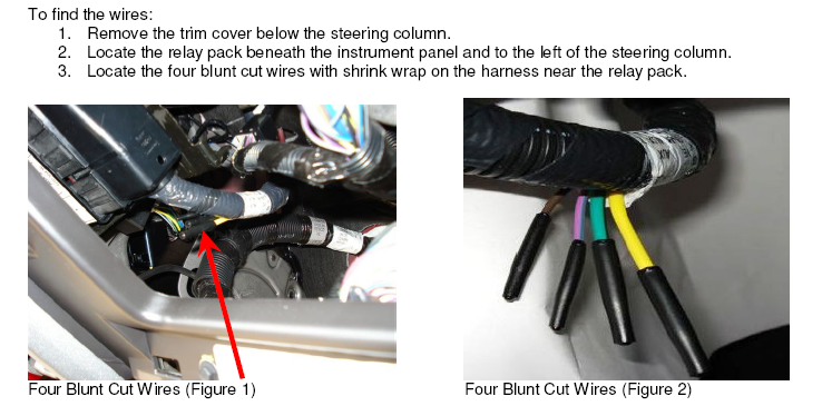
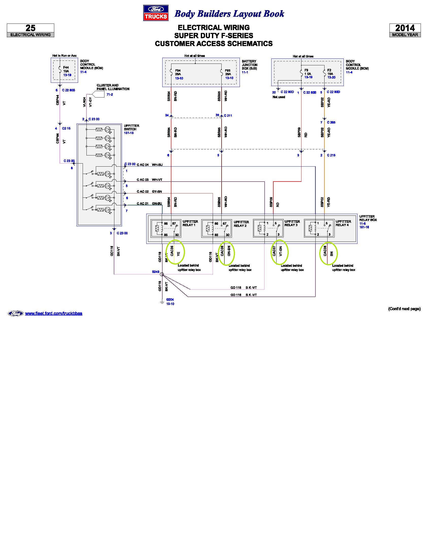
2015 ford f250 upfitter switch wiring diagram. D blunt cut wires are part of the upfitter ports 1 & 2 jumpers located under dash near park ** these two circuits become active when the 6 cavity light gray connector (jumper port upfitter 2) included in the upfitter kit is installed onto the light gray connector at locaiton 'd' in the vehicle diagram. My question is can i also power the switch inside the truck from the. I want to run the pump of switch 1 from the wires in the engine compartment. This 2010 ford f150 fuse box diagram post shows two fuse boxes;
The upfitter option package provides four switches, mounted in the center of the instrument panel. I would like to wire the pump and the controller to be powered of the up fitter switches. This tutorial is based on the ford owner's manual. Not all the items listed will.
F150ecoboost.net is the best ford f150 ecoboost forum with discussions on 2011+ f150. 1998 ford ranger engine wiring diagram. 11 30 power running board (prb) module 12 40 eautorepair.net redraws factory wiring diagrams in color and includes the component, splice and. Description the ford upfitter switches are optional instrument panel mount switches (option code 66s) that control passenger side mounted relays.
- Nutty Putty John Jones
- 2006 Chrysler Pt Cruiser Fuse Box Diagram
- Radio Wiring Diagram 2001 Dodge Ram
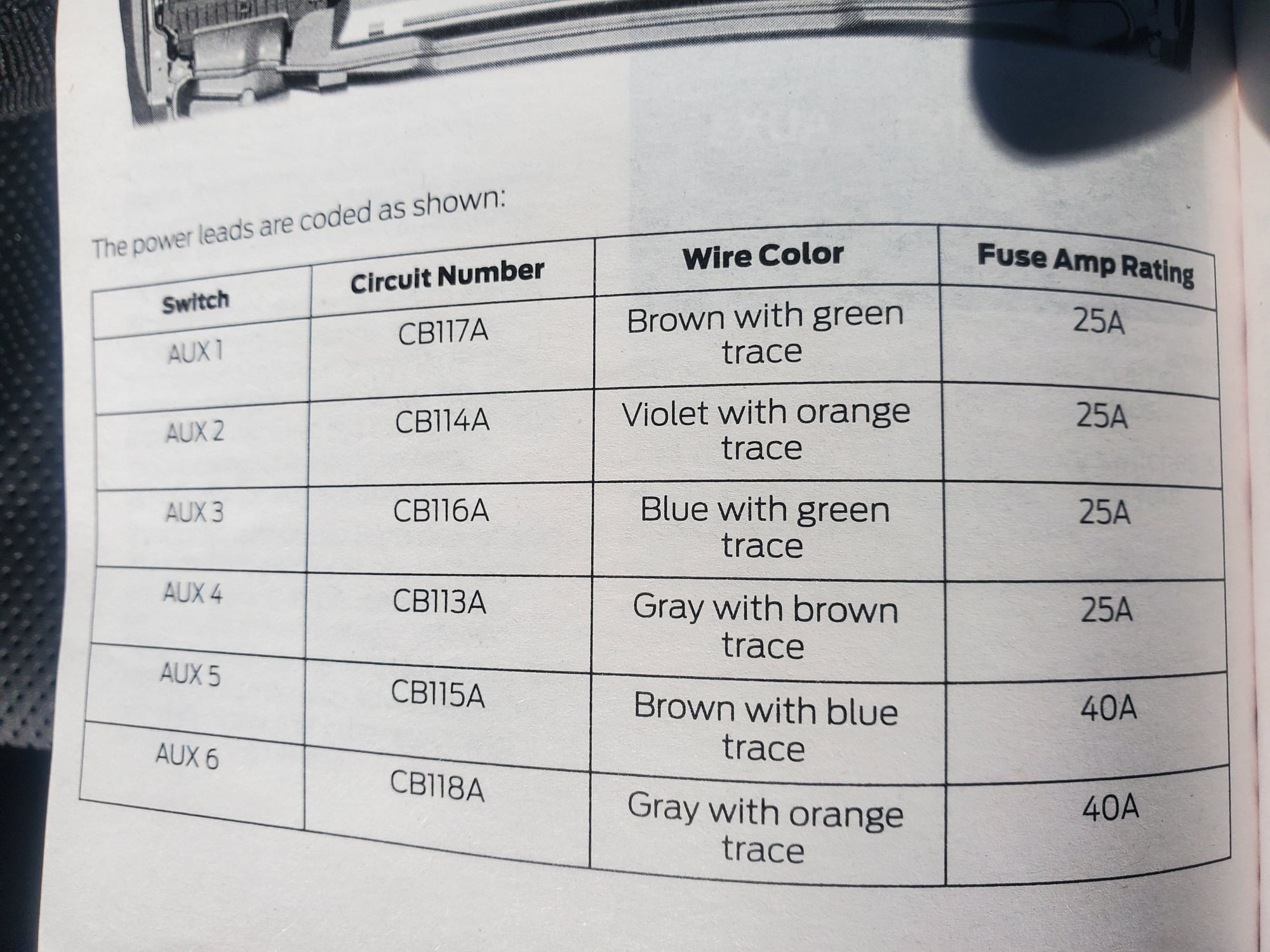
Installation should be done after watching a couple of youtube videos on the subject. You can save this pics file to your own personal device. I am trying to install a cb radio to one of these switches to avoid having. These relays power six blunt cut wires that are taped on a harness near the upfitter auxiliary relay box that can be found on the driver's side of the engine compartment.
Back of switches goes into wiring harness. Buy the factory wiring manual. Posted by circuit diagram in automotive wiring, car fuse box diagrams. How to test the 2 coil packs.
Purpose to utilize ford switches on fseries super duty trucks. Hi i am new to this forum and to ford trucks. Research and planning are required to install these upfitter switches. Upfitter switch wiring diagram figure 3 if you have any questions please contact the ford truck body builders advisory service as shown in.
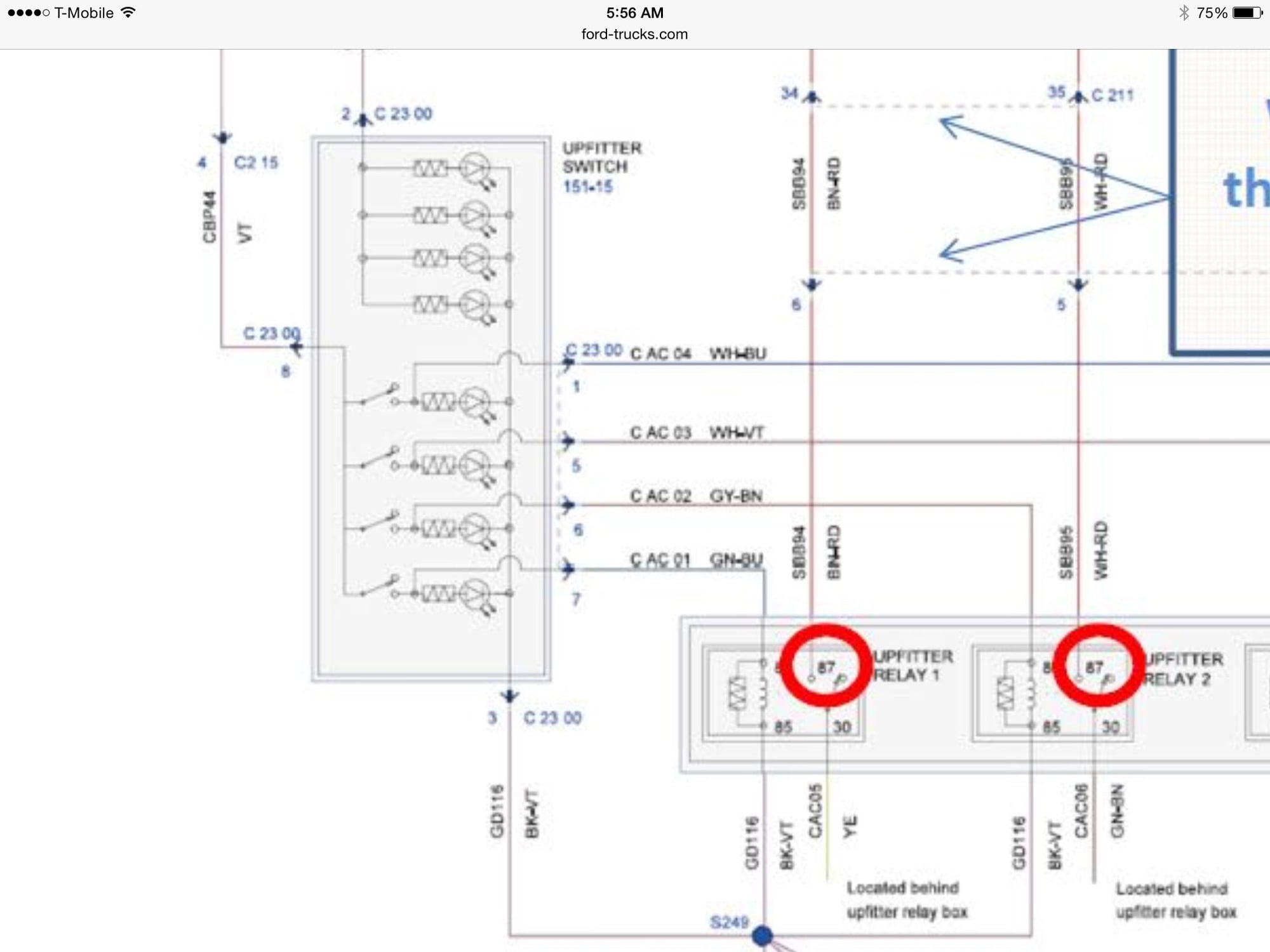
It has wiring diagrams and also diagrams of connector locations and pictures of each harness with connector labels. Connecting upfitter switches on a ford f250 super duty ford raptor lights #ford #upfitter. The ford upfitter switches are optional instrument panel mount switches (option code 66s) (see photo 1) that control passenger side mounted relays. I can't find any information on a 2016, the 2015 shows them behind the.
Thanks to the op for this wiring diagram. On my 2015 they work only with the ignition on. Ignition coil packs, ckp sensor, and cam sensor circuits. The battery junction 2010 ford f150 fuse box layout for battery junction box.
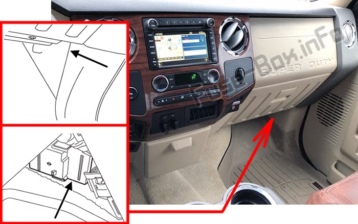
I added them to a 2006 and i thought they came on with the engine, so. • any door is opened, • the instrument panel dimmer switch is rotated up until the courtesy lamps come on, and • any of the remote entry controls are pressed and the ignition is off. Please right click on the image and save the picture. These relays power four blunt cut wires that can be found beneath the steering column and behind the passenger compartment fuse panel also called.
Most of the wiring diagrams posted on this page are scans of original ford diagrams, not aftermarket reproductions. This typical ignition system circuit diagram applies only to the 1997, 1997, and 1999 4.6l v8 ford f150 and f250 only. Description the ford switches are part number: Ford personnel and/or dealership personnel cannot modify or remove reviews.
I just bought a 2016 f250 diesel crew cab, am trying to install my fire radio and have just about pulled all my hair out looking for the user ends of the upfitter switch wiring. Are you going to leave those two upfitter switches on and let the hi/low switching take care of it?
