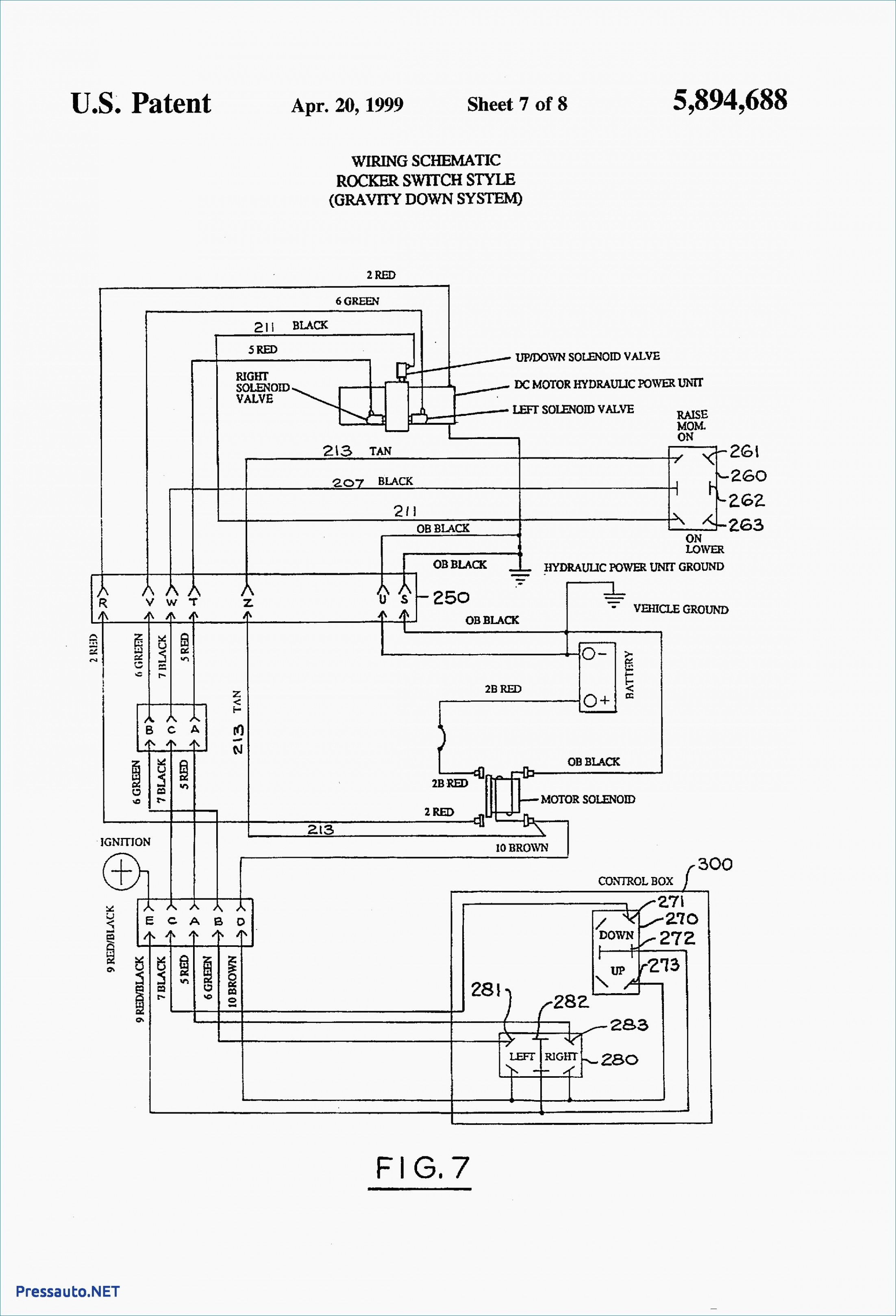
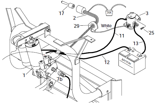
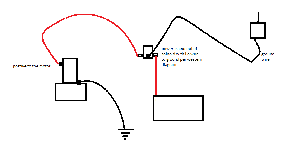
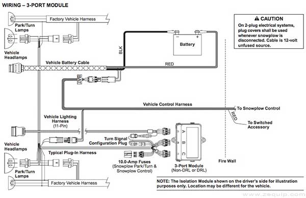
Western Plow Solenoid Wiring Diagram
I have seen failures for both, here are some diagrams (below) and a guide to give you an idea when changing the sensor.
Western plow solenoid wiring diagram. Customize hundreds of electrical symbols and quickly drop them into your wiring diagram. Here are wiring diagrams (below) for the engine and transmission along with a guide to help you do some testing. Oil pan, please do so now. Make and model of abs ecu.
Do u have battery voltage? Vat 48.2 series manual online: Electronics tutorial about the linear solenoid actuator, electromagnetic linear solenoids used as actuators and their duty cycle. Suits all smc ecus ).
Answer this question i have this problem too subscribed to new answers. A wide variety of solenoid valve wiring diagram options are available to you, such as application. If controller and wiring check out, try unscrewing the solenoid and swapping it with a nearby valve of the same model. The complete circuit diagram for solenoid driver circuit is shown in the image below.
To locate the correct wiring diagram for your vehicle you will need: Use wiring diagrams to assist in building or manufacturing the circuit or electronic device. We will understand why it is designed so, once after taking a look at the complete circuit. To do so, you should read and research the trouble codes carefully to understand the problem before starting the troubleshooting.
It is nothing more than a valve controlled by an electromagnet. All electrical components used in a specific system are shown on one diagram. 28, 2007 — electrical circuit diagrams. Both shift solenoids a and b are located toward the rear of the transmission (see photo 3 of 3 in the image viewer).
Remote power units, solenoid packs, remote engine speed controller, p. Alibaba.com offers 401 solenoid valve wiring diagram products. ❮ ❯ just a friendly reminder, if you haven't read the section: Smc twin relay wiring (works to lower battery voltage.
As you can see the circuit is very simple and easy to build, hence we can test this using a small breadboard connection. The ground points circuit diagram shows the connections from all major parts to the respective ground points. Navistar / international wiring diagrams. This tutorial will show you how to hook up a solenoid valve to an arduino using a transistor and write simple code to control it.
They usually come in two flavors : Video on replacing lawn mower solenoids, will be very similar on just about any lawn mower, some may be a little harder to get to, usually located near the. Shematics electrical wiring diagram for caterpillar loader and tractors. Q4:what's the payment term9 a4:
This handy little diagram shows how we will be connecting everything. I read that lead terminal c14 is my tc lockup (solenoid #3), c15 is solenoid #2 and. It is, like relays and motors, an inductive load (aka an ic buster, go read on back emf if it is not already done!). 3ø wiring diagrams diagram dd1.
A wiring diagram is a kind of schematic which makes use of abstract photographic icons to show all the affiliations of components in a system. First, we have to figure out if it's a wiring, shift solenoid, tcm or mechanical fault. Normally open or normally closed. T/t,western union,paypal are applicable for us.
Electrical connection, wiring diagrams solenoids, wiring diagram radiation resistant solenoid, wiring diagrams position indicator. Usually, the electrical wiring diagram of any hvac equipment can be acquired from the manufacturer of this equipment who provides the electrical wiring diagram in the user's manual (see fig.1) or sometimes on the equipment itself there are several possible ways of depicting the solenoid coil. The solenoid should make a distinct click when activated. The study also investigates the thermal behavior of the structure.
Craftsman riding mower model27011 i need to know how the wiring diagram from battery to solenoid to starter is configured. Transmission shift solenoid problems can be very expensive. 3ø wiring diagrams diagram dd3. When troubleshooting a faulty ground point, checking the system circuits which use a common ground may.
Find solutions to your wiring diagram lawn mower solenoid question. Is there an easy way to isolate the trouble from this point. Provides circuit diagrams showing the circuit connections. A magnetostatic study of a solenoid coupled with motion.
The study investigates the effect of the current induced electromagnetic force on the plunger. Better for multiple fuel pumps. Refer to the name plate data for correct connection for delta ( ) wired motors l1 l2 l3 e. In dahlander connection (tapped winding).
Wiring diagrams for autronic products, including engine management, ignitions. Do not touch electrical parts under voltage! Yep, it could be a speed sensor or the solenoid pack.

