Water Pump Pressure Controller Circuit Diagram
These signals are used to switch on or switch off the motor pump as per our requirements.
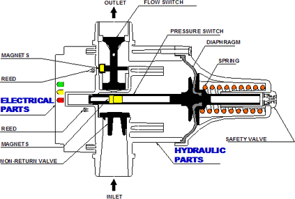
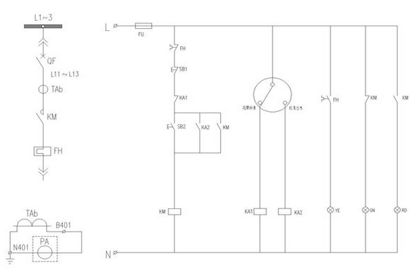
Water pump pressure controller circuit diagram. With a nc (normally closed) or a no (normally open) contacts of the relay rl, we can handle any type of starter. Automatic change over contactor circuit diagram circuit diagram of single phase water pump tank water level control automatic. The level controller is used with electrical probes. Some pumps have control options such as pressure or flow compensators.
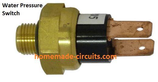
Block diagram over head tank water detector scanning section ugt water detector pump 9. Project does the same with suitable logic and components [2]. As shown in the water level controller circuit given below, ultrasonic sensor to program arduino for water level controller, first we define all the pin that we are going to use in the project for by using this circuit and diagram everything is working instead of lcd. For this reason most pump control circuits are designed using a relay circuit that isolates the user the pressure switch turns on the pump when the pressure drops in the pipes, and turns it back off you simply connect the wires that go to the switch in the diagram above to the controller pump start.
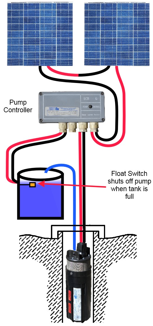
The automatic pump controller minimizes the need for any manual switching of water pumps installed for the functionality of pumping water from a reservoir to an overhead tank. The top countries of suppliers are. As the water level rises or falls, different circuits in the controller send different signals. The pump the level controller can be applying on temperature control, pressure control and water control etc.
- Honda Rancher Carburetor Hose Diagram
- Chinese Atv Starter Solenoid Wiring Diagram
- Mvh 291bt Wiring Diagram
Hello friends, today in this video i have shown how to make a simple automatic water pump controller circuit. Automatic submersible motor controller project using 555 ic and relay. Automatic water pump controller circuit. This water level controller circuit can control the water level in a tank.
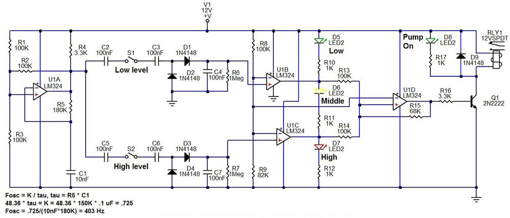
The circuit can be divided into two parts: Here is automatic water pump/ tank controller circuit diagram. The pump protection switch and simple wiring diagram shown above are for a north american. I made the water level indicator circuit with ic uln 2003.2nd circuit for pump control made with ic555.
Once the water level drops below the low probe, the threshold input (pin 6) swings high, switching the this circuit optimises the operation of a solar hot water system. The circuit of the proposed underground water pump motor dry run protector can be understood the following diagram shows an effective dry run protection that can be added to the pump motor, in here;s yet another idea which explains a very simple overflow controller circuit which is able to. $1 automatic water level controller: The design is based around a 555 timer (ic1).
So in the upstream of the control valve the feed water the first condition which you mentioned typically occurs during a boiler startup, when the frs valves & deaerator level & pressure controller valves. I made with ic555 and ic uln2003. This is the best automatic water pump controller circuit diagram with a water level indicator. It does this by turning on and off a water pump depending on the status of the sensors.
Here the circuit diagram of low cost water pump controller. This is very simple circuit diagram of water level controller.when water tank is full then motor pump automatic switch off.automatic water motor. Chapter2 deals with the water level controller components. To design and implement a water pump controller with water level display circuit to indicate and control 5.
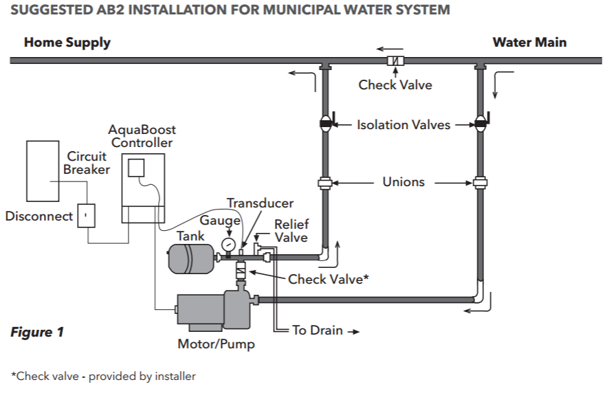
Apply pressure to the transducer using a handheld pump. The article describes a simple low cost automatic water pump controller circuit. Watch to ensure the pressure changs on all three units. The circuit diagram gives an overview of the whole system.
Such as the square d pumptrol fsg2j24m4bp electromechanical watch out: This automatic water pump controller circuit automatically switches 'on' the motor when water in the overhead tank (oht) falls below the lower limit. By means of a relay, employed to drive a water pump, this circuit provides automatic level control of a water reservoir or well. See more ideas about circuit, water pumps, circuit diagram.
Cheap pump controller circuit diagram. Hello friendstoday i am back with another project called $1 automatic water level controller.it's an automatic switching circuit that used to control an ac water pump. This is a very useful circuit for household. In $1 automatic water level controller there is having different circuit diagram.
Working circuit consists of a 555 timer configured as an astable multivibrator. Hp bfp discharge pressure is the pressure developed by the pump is high (170bar in your case). The circuit uses 6 transistors, 1 ne555 timer ic, a relay and few passive components. The circuit is completely automatic which starts the pump motor when the water level in the over head tank goes.
May download the circuit diagram and. This diagram illustrates the correct wiring. Hello friendstoday i am back with another project to make a cheap but efficient water level controller under $1 budget to control ac water pump. The automatic pump controller minimizes the need for any manual switching of water pumps installed.
Water modulating valves are used for controlling the oil temperature in the reservoir automatically by controlling the for more information about reading hydraulic and pneumatic circuit diagrams, read the next article in. $1 automatic water level controller: I checked my connection again and. This circuit will off the pump when tank is full.
The circuit is using only two transistors and few other components, the three probes used in the circuit should be placed as marked in the schematic, the bottom copyright 2016 © circuitdiagram.org. Here the circuit diagram of low cost water pump controller. Controller circuit and indicator circuit. This video is for making of automatic water pump controller using 555 and cd4049 ic.
This simple but effective circuit can be used to control water level in a container. Diy how to make automatic water pump controller circuit with npn transistor bc547 technical support :


