Trim Sender Wiring Diagram

Diagram Mercruiser Trim Sender Wiring Diagram Full Version
Trim Pump Wiring Diagram Cm Flatbed Wiring Diagram

Diagram Wiring Diagram Hurricane Deck Boat Panel Full
I have an old (1989) yamaha 50deto and as part of my winter work i am trying to hook up a multifunction gauge i picked up from ebay to the engine.
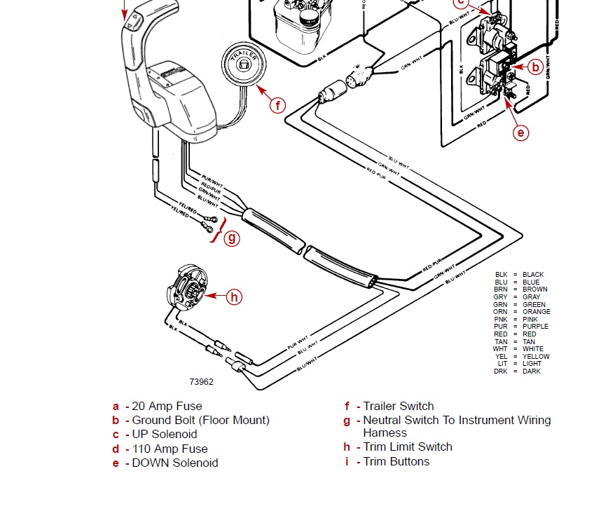
Trim sender wiring diagram. This diagrammed trim sender connection may or may not be the same for your year model but it appears to show one sender black sender wire going to harness black to neg. When the pump operates in the downward mode, the. Looking at the back of the gauge in the dash it. Trim and tilt motors and parts for mercruiser sterndrives.
About 1% of these are auto sensors, 0% are auto switches, and 0% are other motorcycle body systems. Tighten screws securely and fill grooves with figure 7 is a functional diagram of the down circuit. They are sold in a package of 1 each. Power trim wiring diagram a b c d e f g h.
All formats available for pc, mac, ebook readers and other mobile devices. Trimsync will be connected in line with the trim sensors and the factory display/indicator (if equipped) functionality will be retained. 2000 bayliner capri ls wire fuse box diagram 2000 bayliner capri ls wire fuse box map fuse panel layout diagram… Connect wires to a gauge, following diagram.
- Dometic 9100 Power Awning Parts List
- 2014 Vw Jetta Tdi Fuse Diagram
- Drive Belt Diagram For Husqvarna Zero Turn Mower
Align tab on end of trim sender shaft with slot in cross pin. The transom assembly and sterndrive unit are equipped with a ground wire circuit to ensure good electrical continuity between engine, transom assembly and sterndrive components. Engage tilt lock level (a). Wiring diagrams show the interconnection of the multicore cables, for example, between the switchgear and the associated control panels, and the these diagrams are required to facilitate the wiring of the measurement, protection and control equipment at the substation construction stage.
It shows how the electrical wires are interconnected and can also show where fixtures and components may be connected to the system. This limits how far up the drive will trim. The pointer of whatever gauge you are checking should be at the position shown in the upper portion of the diagram at right. Ground , and the other sender black to harness brown/white to.
Trim sender units the trim senders are no longer sold individually. Next, take a short wire and connect to sender terminal and ground terminal (shorting sender terminal to ground). Disconnect the indicator leads from the terminal block on the 3. Mount trim indicator gauge, as shown.
Download mercruiser trim sender wiring diagram for free. The first component is emblem that indicate electric component from the circuit. How to wire fuel gauge and sending unit complete explanation. Mercruiser did this because bad wires were the leading cause for switch failure.
Mercruiser trim sender & limit switch replacement. Remove the gauge's sender wire. Mercruiser trim sender wiring the hull truth boating and. Fresh tilt and trim switch wiring diagram.
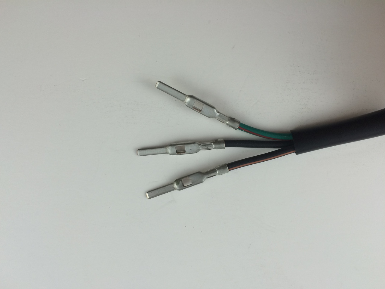
S for the sender, g or. The sending wire leads off the center post; A wiring diagram is a simple visual representation of the physical connections and physical layout of an electrical system or circuit. Later production, by, wt, ef, 2 wire.
Commander series side mount remote control. Also, disconnect trim sender wires at the engine harness. Route new trim limit switch wires through hole. Connected the trim sender wires from the lower unit to the brown/white and black wires which match the original wiring connections.
If installing on boat that is equipped with merruiser stern drive, rown/white wire is connected to trim sender terminal block. Mercruiser trim sender limit switches wiring diagram. Power tilt and trim wiring wiring diagram schematic name mercruiser trim sender wiring diagram the diagram offers visual representation of a electrical arrangement. Maintain light tension on the.
A wide variety of trim sender options are available to you Bring together the two grommet halves and ensure they are seated tightly in the hole and that the flat edges that mate together are vertically aligned. The other wire runs to ground. I am hoping i can pick the collective brains of the forum regarding some old yamaha electronics.
The port switch is the trim limit switch. Easy to find parts & order online. Torque he) nuts to 10 ibs. Collect all useful circuits for you.
The trim gauge on my 96 chaparral 2130 has never functioned properly its either all down or all up nothing in between.
Gallery of Trim Sender Wiring Diagram

Diagram L7 Solo Baric Wiring Diagram Full Version Hd Quality

Diagram Mercury Power Trim Wiring Diagram Full Version Hd
Diagram Yamaha Outboard Tilt And Trim Gauge Wiring Diagram

Yamaha Outboard 130 Hp L130txrr Power Trim Sender

Diagram Diagram Mercruiser Trim Sender Wiring Diagram Full

Diagram Omc Trim Pump Wiring Diagram Full Version Hd Quality
Trim Tilt Wiring Question Again
Diagram 120 Mercruiser Ignition Wiring Diagram Full Version
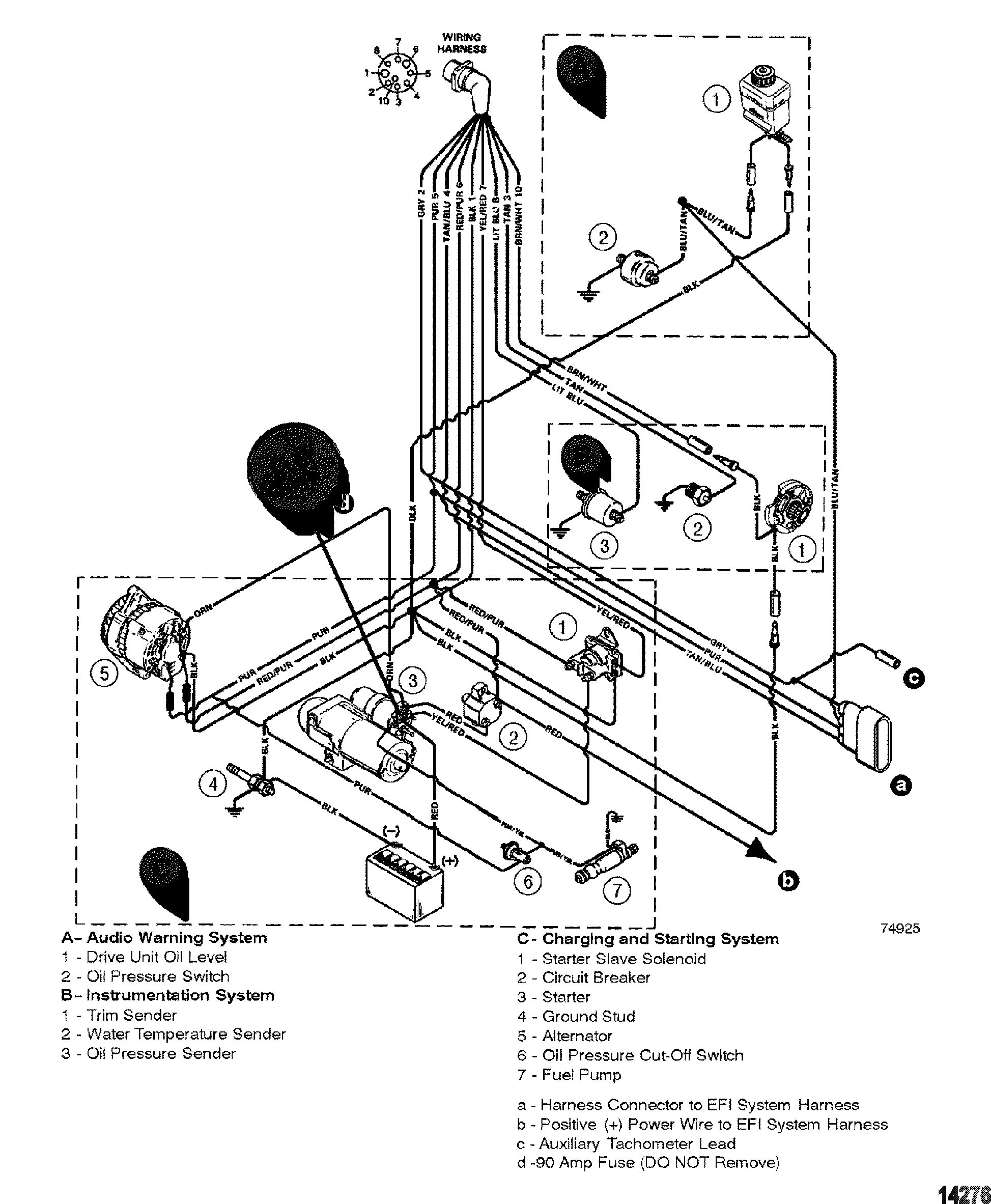
Diagram Pyrometer Sender Wiring Diagram Full Version Hd
Viewing A Thread 2 Wire Motor Trim Wiring Diagram

Ed 1687 Trim Position Sensor Wiring Diagram Trim Senders
7d30 Mercruiser Trim Sender Wiring Diagram Digital Resources
Diagram Diagram Mercruiser Trim Sender Wiring Diagram Full
Diagram 2 Wire Power Trim Wiring Diagram Full Version Hd

Volvo Penta Exploded View Schematic Trim Senders And Gauges
269 95 Genuine Volvo Trim Sender 3 Wire 21484383 In Stock Amp Ready To Ship
Diagram Diagram Mercruiser Trim Sender Wiring Diagram Full
