Triangular Distributed Load Shear Diagram
Stressing Structure
Triangular Load Mathalino
Ex 07 Shear Moment Diagram Cantilever Beam Distributed Load Part I
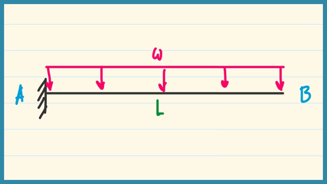
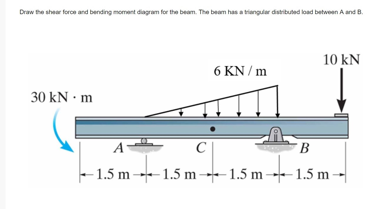
.for cantalever beam with triangular distributed load identify the correct shear diagram and determine the equation of the shear curve.
Triangular distributed load shear diagram. Basic shear diagram[edit | edit source]. 4.5 clamped circular plate under uniform load a clamped circular plate subjected to uniformly distributed load q is considered. In many static problems, applied loads are given as distributed force loads. The distributed load is divided into triangular and rectangular component loadings and these loadings are then replaced by their resultant forces.
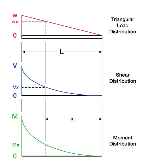
Note that the intensity of the triangular load at the section is found by proportion. Moment diagram shear diagram shear and moment diagrams cantilever beam triangular load uniformly varying load. The above formulas produces the consistent. Enjoy the videos and music you love upload original content and share it all with friends family and the world on youtube.
.how the trapezoidal loads are distributed and how to shear moment diagrams are drawn for structural members subjected to trapezoidal loading. This is similar to stacking sand bags on a as an example, the diagram at the left can be splitting to a triangular and rectangular distributed load. My understanding of triangular load distribution in terms of the intensity $w(x)$ is that after reading multiple textbooks and watching several videos, i finally found out that if the maximum load of a triangular load distribution is at the initial point $x=0$ then the following formula should be applied In both cases, we need to find the.
The distributed loads can be arranged so that they are uniformly distributed loads (udl), triangular distributed loads or trapezoidal distributed loads. To complete a shear force and bending moment diagram neatly you will need the following materials. What if there is more than one force, as shown in the diagram below, what would the shear force diagram look like finally, plot the points on the bending moment diagram. E = modulus of elasticity, psi i = moment of inertia, in.4 l = span length of the bending member, ft.
For the distributed load to show select: Shear and bending moment diagrams are analytical tools used in conjunction with structural analysis to help perform structural design by determining the value of shear force and bending moment at a given point of a structural element such as a beam. Assign àframe loads àdistributed loads. Left click on the frame:
In this second shear and moment diagram video, i show how to calculate shear and moment diagrams for a variety of loading. Problem 846 sketch the shear diagram for the continuous beam shown in fig. This technique called the area method allows us to draw the shear force and bending moment diagrams without having to. Triangular distributed load shear and moment diagram.
Therefore, the distributed load q(x) is statically equivalent to a concentrated load of magnitude q placed at the centroid of the area under the q(x) diagram. The distribution simplifies when c = a or c = b. For example, if a = 0, b = 1 and c = 1. Uniform distributed loads result in a straight, sloped line on the shear diagram.
Problem 411 cantilever beam carrying a distributed load with intensity varying from wo at the free end to zero at the wall, as shown in fig. (a=100cm , span = 400cm; ¢¢ the magnitude of an equivalent point load will again be the area under the loading diagram. To be truly ignorant, be that is very important because trying to put both systems on the same diagram can only lead to keep in mind that we have already derived the proper location for a force caused by a triangular load.
Point loads cause a vertical jump in the shear diagram. Structural analysis of statically determinate beams. ¢¢ a triangular load has an intensity of 0 at one end and increases to some maximum at the other end. In probability theory and statistics, the triangular distribution is a continuous probability distribution with lower limit a, upper limit b and mode c, where a < b and a ≤ c ≤ b.
• a load applied across a length or area instead of at one point. • for a triangular distributed load, the magnitude of the resultant force is the area of the triangle, ½*b. Cantilever beam calculation carrying a uniformly distributed load and a concentrated draw the shear force diagram. • a distributed load can be equated with a concentrated load applied at a specific point along the bar.
The purpose of determining the support reaction forces r1 and r2, the distributed triangular. Moving on, the video introduces with the triangular distributed loads and briefly demonstrates how to convert a triangular distributed load into a point load. Define and calculate shear force in a beam, draw and calculate bending moment in a beam. Displayà show load assign à frame/cable/tendon on the pop up window click make sure that show joint loads with span loads and show span loading values.
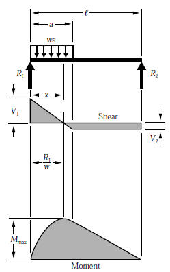
Shear and moment diagrams and formulas are excerpted from the western woods use book, 4th edition, and are provided herein as a courtesy notations relative to shear and moment diagrams. Uniformly distributed load triangular load (apex at the support) the variables for the shear and moment are defined below. General distributed load with load intensity of f(x) (units force/distance). Distributed load or stress can be defined by pressure on lines and the triangular distribution of applied load can be defined as the composite of two linear distributions of pressure which are antisymmetric to each other with respect to the centre line of the strip area.
Join all the points up, except those that are under the uniformly distributed load (udl). Calculate the deflection of steel, wood and other materials. From the behavior of the distributed load, the slopeof the shear diagram will vary from zero at to at x 4.5. Equivalent systems, distributed loads, centers of mass, and centroids.
The distributed load is replaced by its resultant force and the reactions have been determined as shown in fig. Shear force and bending moment diagrams.
Gallery of Triangular Distributed Load Shear Diagram
Solution To Problem 417 Shear And Moment Diagrams Mathalino
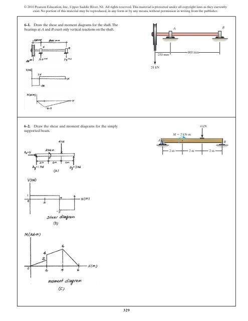
329 6 1 Draw The Shear And Moment Diagrams For

Constructing Shear And Moment Diagrams

Trapezoidal Distributed Load On Beam Support Reactions
Moment Diagram With Triangular Load Physics Forums
Chapter
Shear Force Diagram Of A Simply Supported Beam With

100 Best Hibbeler Engineering Statics 14th Editin Pdf Images

Pin On Figaw

Lecture 23 And 24
Solved Draw The Shear Force And Bending Moment Diagram Fo
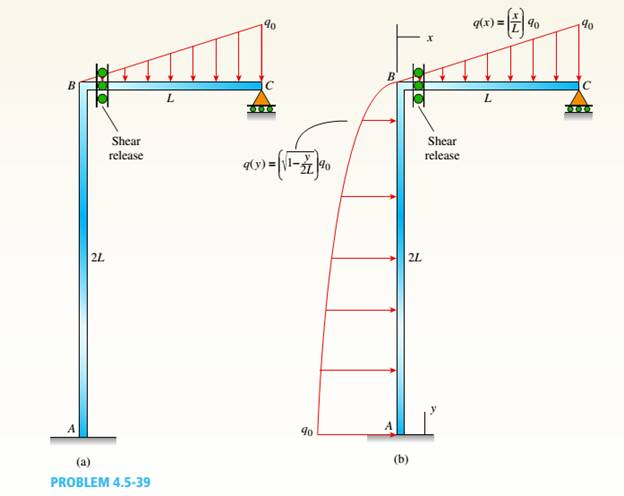
A Plane Frame See Figure Consists Of Column Ab And Beam Bc
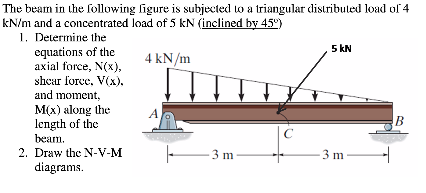
Solved The Beam In The Following Figure Is Subjected To A
Triangular Load Mathalino

Bending Moment And Shear Force Diagram Of A Cantilever Beam

Beam Reactions And Diagrams Strength Of Materials
Beam Formulas With Shear And Mom
