Timer Switch Circuit
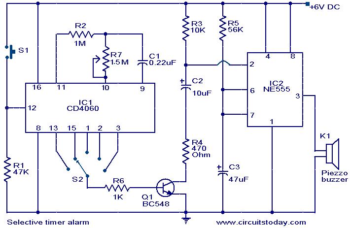
Selective Timer Alarm
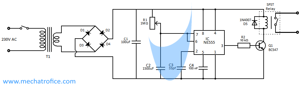
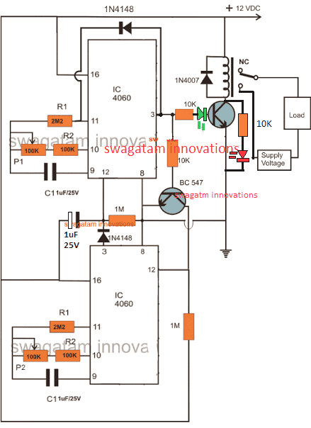
How To Build Relay Timer Switch Circuit Diagram
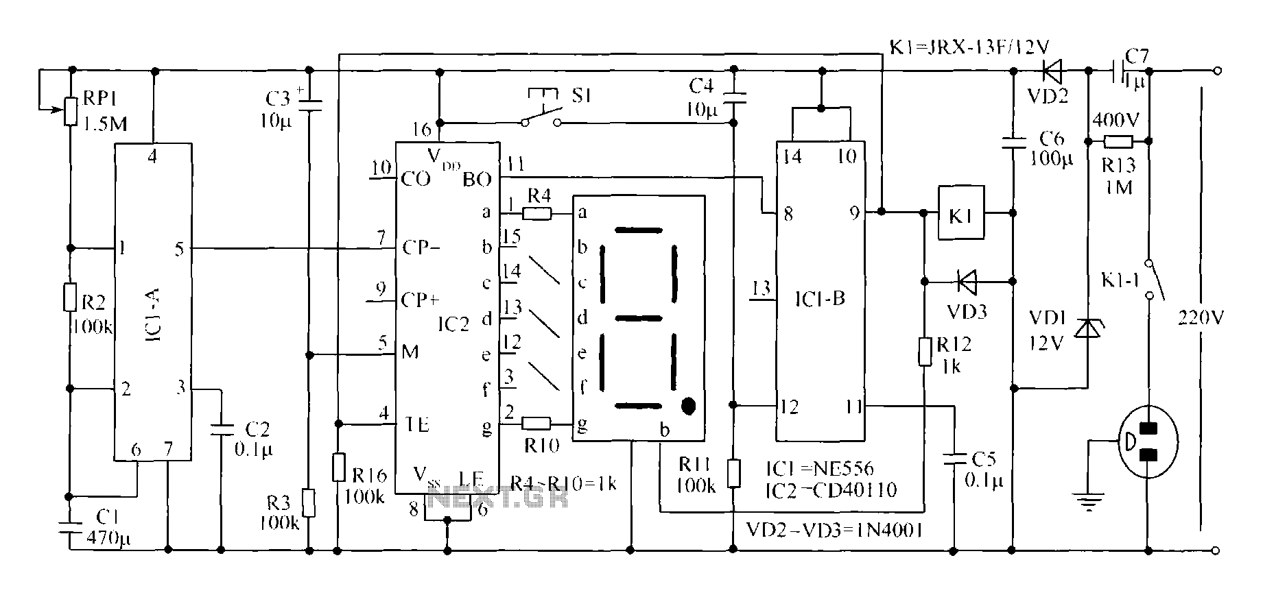
Novel Circuit Diagram Of The Timer Switch Under Timer
Sequential timer circuit play a significant role in all sorts of timer applications such as switching devices in sequence for a given amount and switch appliances off after desired.
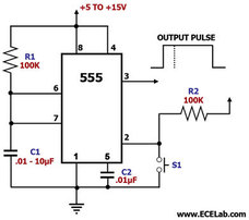
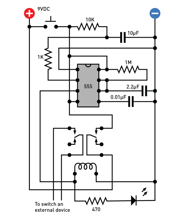
Timer switch circuit. Last updated on december 13, 2019 by swagatam 39 comments. For each successive clap t6 conducts and cuts off alternately , resulting and on of switching for the lamp. Here a simple circuit diagram of a timer switch circuit is given. In fig.1 see a 100 second delayed turn on relay rl1 switch, if plug power +12v in circuit.
Capacitors c2 and c4 are used to filter noise in. With this information you will learn how how the 555 works and will have the experience to. This circuit is based on the principle of bistable mode operation of 555 timer. Timer circuit timer on/off circuit how to make timer circuit timer circuit with time selector timer relay is a time dependent magnetic switch.you will learn completely in this video about its use.
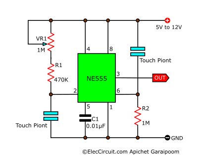
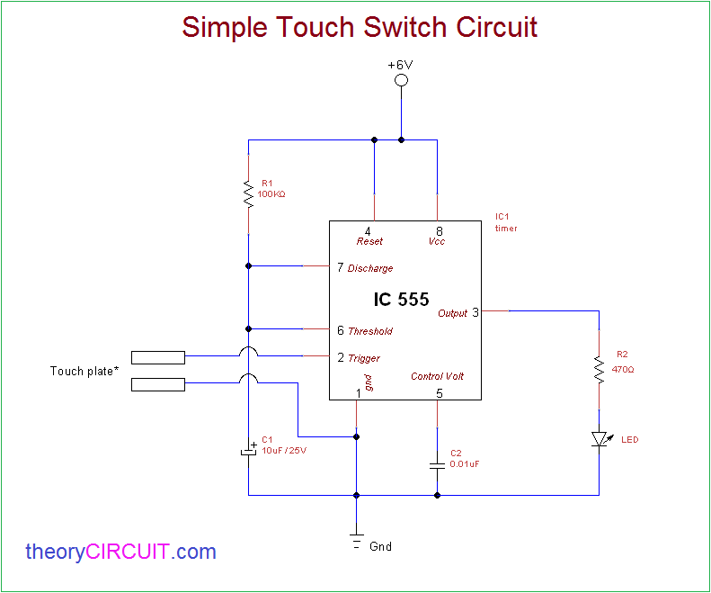
Start date sep 14, 2011. Discover over 927 of our best selection of 1 on. In this simple touch lamp switch circuit, we have used timer ic 555 operated as on and off. In this mode, the timer output is either high or low depending upon the status.
A simpler option can be in the form of a mosfet switch, let's learn the circuit details of the same. Automatic changeover switch circuit principle: The clap switch circuit is yet another simple and cool project. Dosto iss circuit ko aap kaafi aasani se ghar par hi bna sakte hai.
A time switch (also called a timer switch, or simply timer) is a timer that operates an electric switch controlled by the timing mechanism. This switch on delay timer is very useful for protection. The timer activates a relay through a bipolar transistor in order to connect or disconnect the device we want to control. Tiny timer light switch presented here is a simple transistorised electronic timer which drives a high efficiency white led for a finite time out.
When the push button switch is pressed the led will be glow for a time duration. The 555 timer is a simple integrated circuit that can be used to make many different electronic circuits. The output signal from the 555 timer ic is used as a clock for a 4017 decade counter. Without trying to hack into the tracker, my plan is to put a timer switch on the external power supply i would like a simple circuit which, when the ignition is turned off, would connect/disconnect power for.
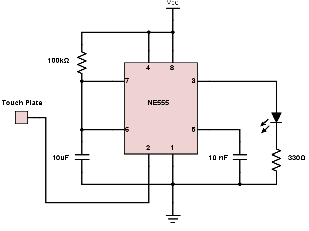
Intermatic introduced its first time switch in 1945, which was used for electric signs, store window lighting, apartment hall lights, stokers, and oil and gas burners. This circuit was developed since a number of visitors of this website requested a timer capable of as shown in the circuit diagram, sw1 is a 1 pole 9 ways rotary switch. This simple touch switch is developed by using 555 timer ic operated as a monostable vibrator. Basically in this circuit we will have a led which turns on when we touch a pin of timer.
By using this circuit you can turn on and off a device by simply touching the touch plates or metal. So in this tutorial, we are going to make a simple step by step clap switch circuit using 555 timer ic. When the period has expired a latching relay disconnects both the. If you want to switch on any load after some moment or some duration then you can use this timer circuit.
The simple touch free timer switch circuit presented here can be operated by moving your hand in front of it. Meter using a 555 timer as a monostable circuit, it is easy to build a good switch debouncer circuit. 2,030 circuit timer switch products are offered for sale by suppliers on alibaba.com, of which timers accounts for 3%, time switches accounts for 1%, and push button switches accounts for 1. Dosto iss video me mai aapko ek delay timer switch circuit bnakar dikhane wala hu.
This page contain electronic circuits about timer circuits at category timer circuit page 4 : 1 shows the circuit of the touch free timer switch.
Gallery of Timer Switch Circuit
Auto Power Cut Off Timer Circuit
555 Timer Switch Debouncing Circuit Timer
8 Simple Touch Switch Circuit Projects Eleccircuit Com
Pcb Layout Tips For A Clap Switch Circuit Pcb Design Blog

Periodic Timer
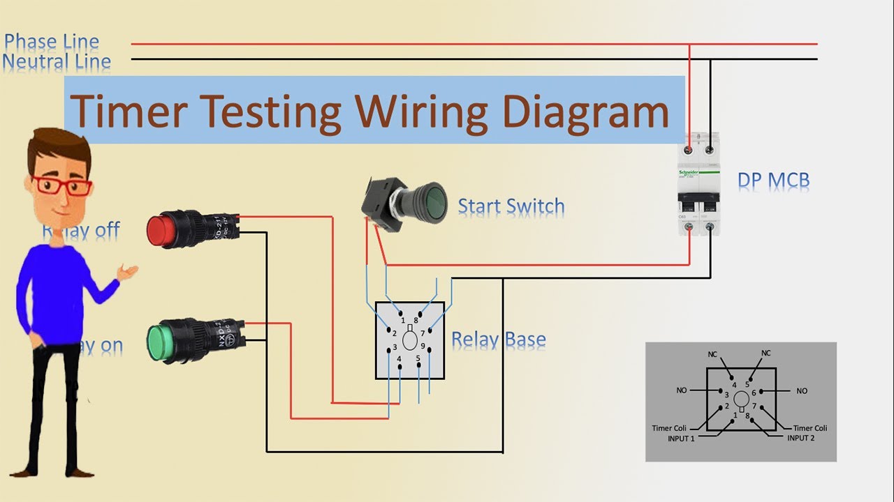
Timer Testing Wiring Diagram Timer Timer Wiring Timer Wiring
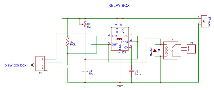
Timer Switch Using 555 And Relay Easyeda

How To Build Relay Timer Switch Circuit Diagram
555 Timer Monostable Circuit Calculator Electrical

R C Timer Switch For Radio Control Applications
Simple Programmable Timer Circuit Homemade Circuit Projects

Manhua Mt316s G Timer Switch Circuit 6v 12v Buy Timer
Simple Touch Switch Circuit

Timer Switch Circuit Diagram For Light Circuit Diagram
Lighting Circuits Connections For Interior Electrical
Build A Delay Timer That Doesn T Suck Energy Make
Time Switch Fiat Timer Electrical Switches Circuit Breaker
