Timer Switch Circuit Diagram
R C Timer Switch For Radio Control Applications
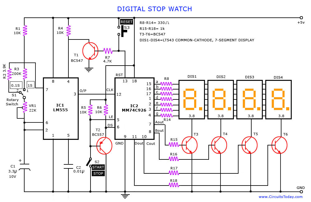
Diagram Electrical Timer Diagram Full Version Hd Quality
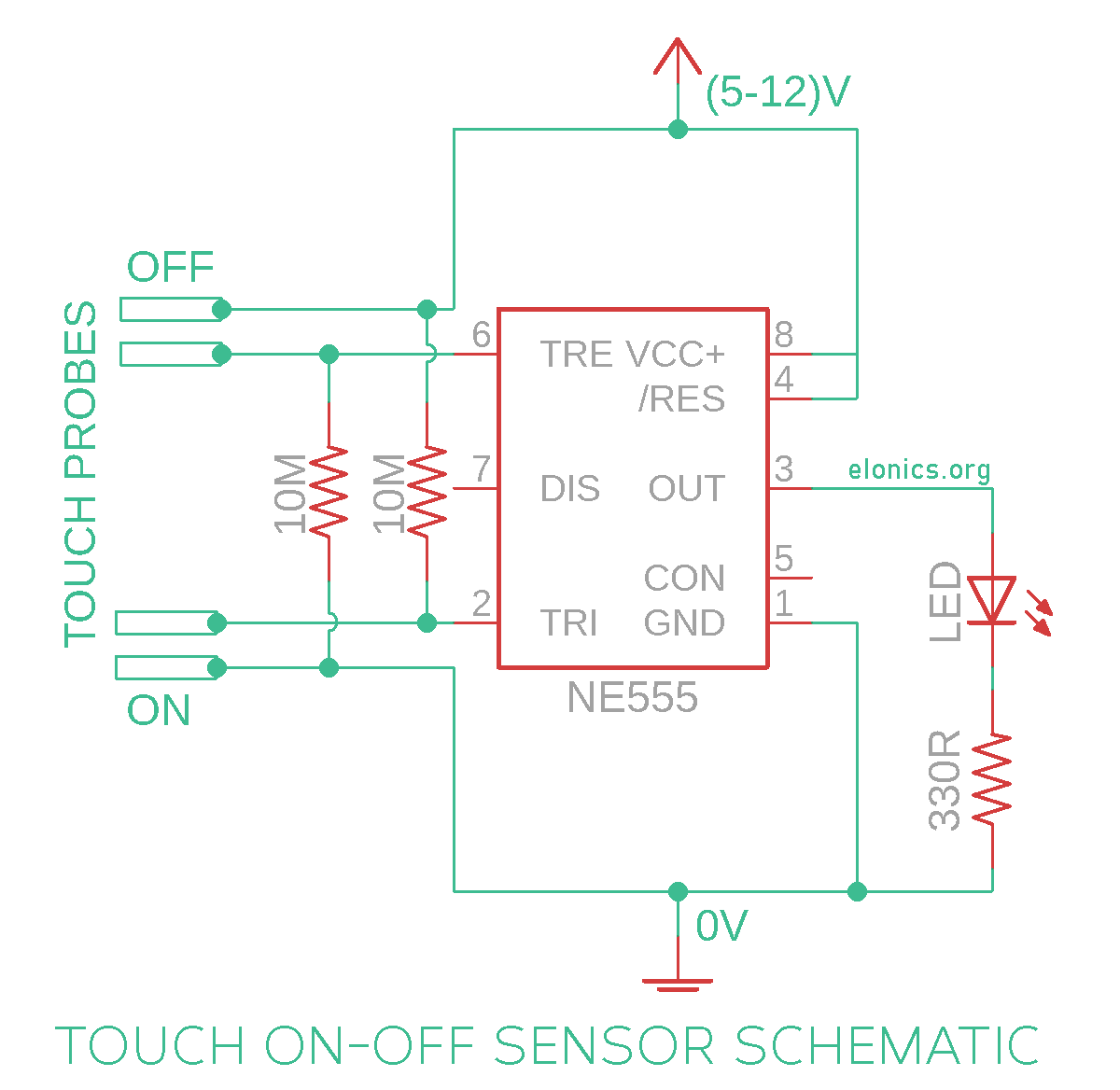
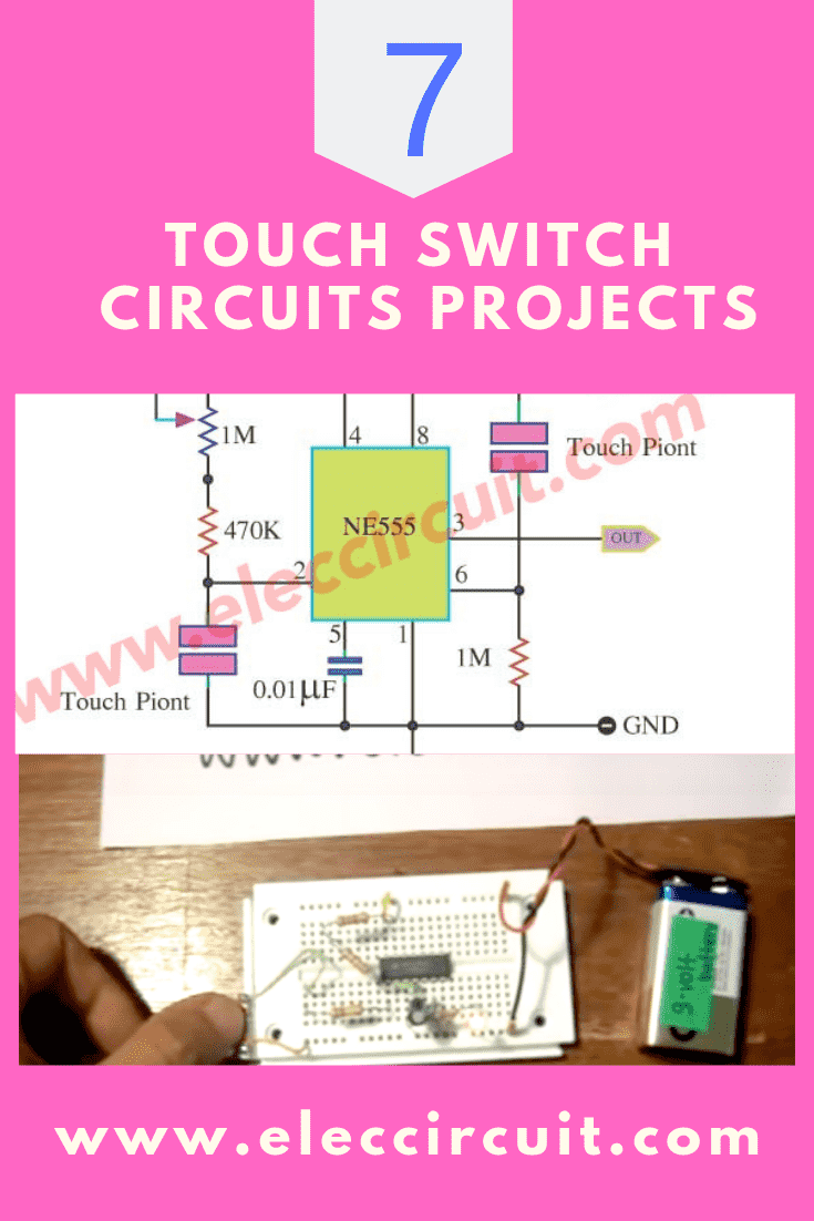
Touch On Off Sensor Switch Circuit Using 555 Timer Ic Elonics
Push button = push to on switch circuit design requested by mr.bourgeoisie:
Timer switch circuit diagram. On the last diagram we see two. We are listing a curated collection of 555 timer circuits and projects published in our site before. The complete details about the circuit and its circuit diagram are given in the original article. This mode outputs an oscillating pulse signal.
Timer switch circuit diagram shown in figure: Single transistor timer circuit tutorial for beginners in electronics. This circuit uses a relay and a sensor to sense and switch when the light intensity crosses a certain limit. Automatic changeover switch circuit principle:
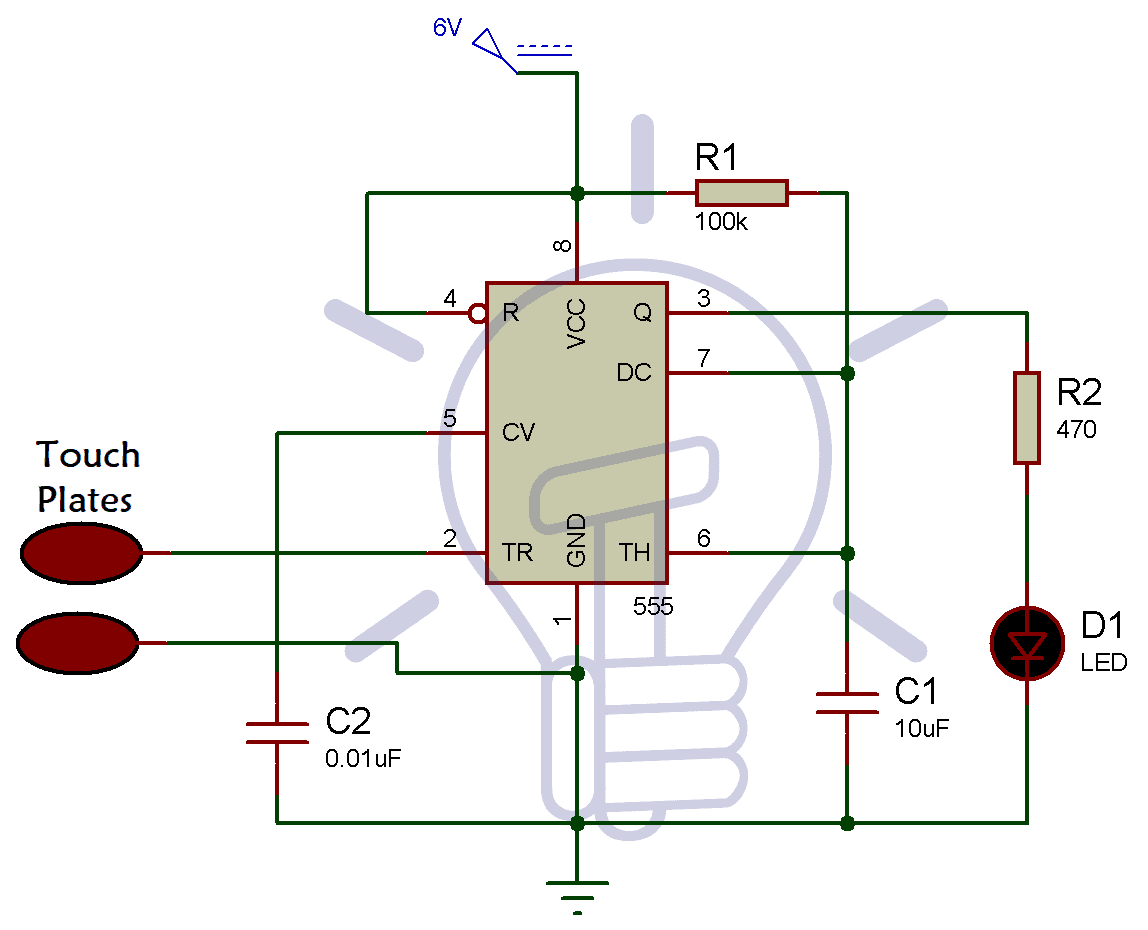
As shown in the diagram two touch plates are connected. Monolithic circuit shown in fig time transmitter circuit xr2242, timing time from a few milliseconds to a few days. Here a simple circuit diagram of a timer switch circuit is given. A touch switch is a type of switch that only has to be touched by an object to operate.
The aove figure shows the circuit diagram of touch switch. Tiny timer light switch presented here is a simple transistorised electronic timer which drives a high efficiency white led for a finite time out. When the push button switch is pressed the led will be glow for a time duration. This simple touch switch is developed by using 555 timer ic operated as a monostable vibrator.
Please connect the buzzer or the load between pin#3 and ground, and not between pin#3 and positive as incorrectly shown in the above diagram. The output switches between high and low states at a tunable frequency and pulse width. The simple touch free timer switch circuit presented here can be operated by moving your hand in front of it. Easy beginner electronic circuit that can be built on breadboard.
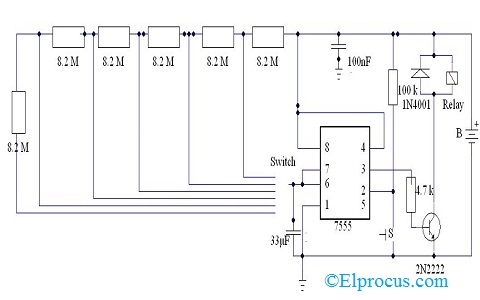
Timer relay is a time dependent magnetic switch.you will learn completely in this video about its use, application,timer relay circuit. The required components are given below circuit diagram: Let's make a simple arduino switch. The circuit comprises a time base oscillator, a binary counter 8 and a control trigger.
You may need the datasheet & pin configuration diagram of the ne555 timer ic. As shown in the circuit diagram, sw1 is a 1 pole 9 ways rotary switch. This is a simple electronic project and mostly used to turn on and off ac appliances with the help of sound. The timer activates a relay through a bipolar transistor in order to connect or disconnect the the next two diagrams show the proposed pcb for this circuit and an image of what would be the finished circuit.
It is very useful way to run your devices for specific time. The glow time can be increased or decrease by the potentiometer. Main part of this circuit is timer ic 555 and others are few easily available components, to give turn on this circuit by closing s1 switch and choose the timer range by closing s3, s4, s5 or s6 switch then push the start switch s2 and wait, the buzzer gives alarm sound depends on the timing range. The circuit works off 12 volt dc supply.
Let's make a simple arduino switch. Parts list for touch switch circuit diagram using ic 555. [view plants watering watcher circuit diagram]. Hi , this video is to show you how to make a simple timer switch with transistor bc547.
You can watch the following video or read the written tutorial below. The resetting time of the timer is the period of time during which all the internal components including the contacts, pointer, and the circuit components, such as the capacitor, of the. Here the stable stage is low, so the timer outputs low after the trigger is removed. 📌 download the circuit diagram.
Connected appliance with this timer circuit is automatic switch off after some duration of time. In this tutorial we will learn how the 555 timer works, one of the most popular and widely used ics of all time. How to make a delay timer switch hi friends in this video i have made a delay timer switch circuit you can control ac and. The voltage supplied in this circuit must not exceed 6v.
The 555 timer, designed by hans camenzind in 1971. 1 shows the circuit of the touch free timer switch. Push on push off relay switch. 555 timer timers, as the name specified, are the electronics circuits used for measuring time intervals.
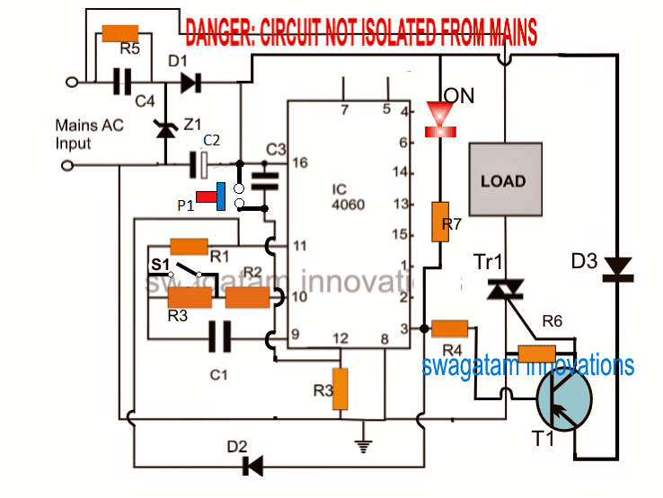
Lm555 timer internal circuit block diagram. Timer circuit with relay switching. The clap switch circuit is yet another simple and cool project. Pin#2 of the 4017 ic is.
The circuit must switch off after 20 secs. This circuit was developed since a number of visitors of this website requested a timer capable of emitting a beep after one, two, three minutes and so on, for. This timer circuit is designed to switch on a 12 v load. Technical explanation for timers and time switches.
Working and schematic diagram of clap swith circuit. Timer circuits used to provide time delays for triggering, types of timer circuits, ic 4060, fridge timer, industrial timers, long duration timer below are few examples of timer circuits used in different applications. A simple timer circuit can be built by using only a single or two transistors. When the circuit is powered by a 9v battery, the led switches on.
You can see it in circuit diagram. Have you used the same circuit diagram for implementing it practically? A switch (or link on the breadboard) is closed to start the timer causing the led to switch off for a. In monostable operation the output is given by the 555 timer is one shot.
The delay duration can adjusted with the changing the this connection of circuit is called the monostable mode of operation. In this simple touch lamp switch circuit we have used timer ic 555 operated as on and off. Or google any sample relay circuit for your understanding. This circuit is based on the principle of bistable mode operation of 555 timer.
Time is set by potentiometer r2 which provides a range or 1 sec. Working on the touch lamp switch.
Gallery of Timer Switch Circuit Diagram

555 Timer Tutorial The Monostable Multivibrator
Simple Touch Sensitive Switch Circuit Using 555 Timer Amp Bc547
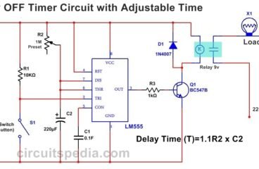
Delay Timer To Switch On Switch Off Circuitspedia
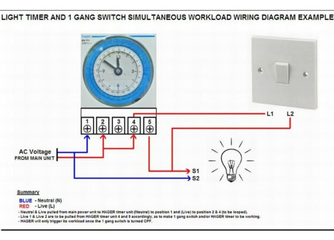
Diagram Leviton Timer Switch Wiring Diagram Full Version Hd

Diagram 240v Water Heater Timer Wiring Diagram Full Version
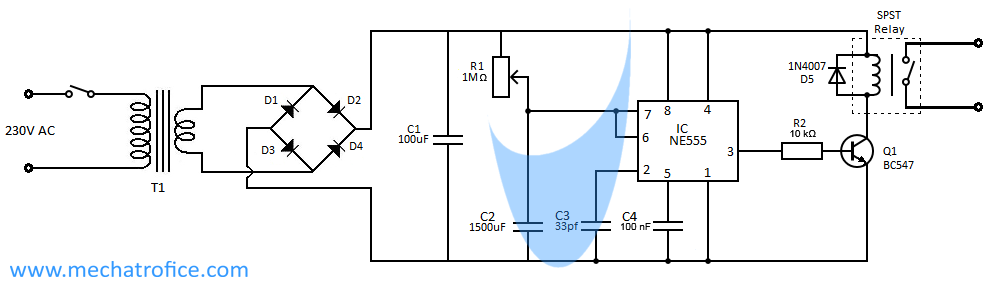
Auto Power Cut Off Timer Circuit
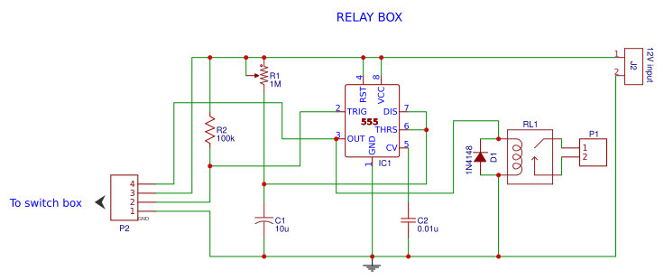
Timer Switch Using 555 And Relay Easyeda
8 Simple Touch Switch Circuit Projects Eleccircuit Com
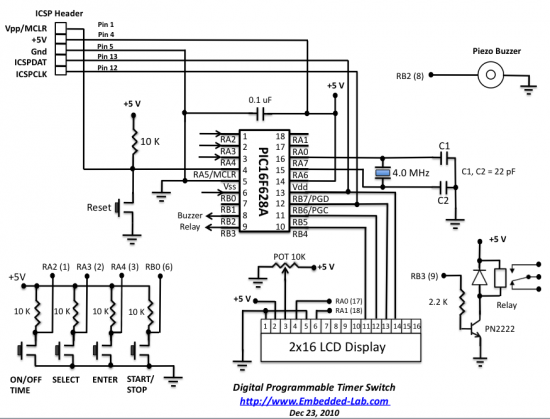
Programmable Digital Timer Switch Using A Pic Microcontroller

Hg 3057 Switch Circuit Diagram On Digital Programmable Timer

This Post Is About The Staircase Timer Wiring Diagram In The
30 Minute Timer Circuit Using 555 Ic And 7555 Ic
Make This Geyser Water Heater Timer Circuit With Automatic

Two Simple 24 Hour Timer Circuit Schematics
12v Relay With Timer Switch 4 Steps Instructables

Touch Lamp Switch Circuit Using Timer Ic 555 Envirementalb Com

Simple Timer Circuit Diagram
