Stop Start Switch Wiring Diagram

Structure 3 Wire Start Stop Switch Wiring Diagram Full
Install Motion Pro Start Stop Switch Honda Grom

How To Convert A Basic Wiring Diagram To A Plc Program Realpars
This allowed me to get the correct size for the hole next is joining the some of the wires together.
Stop start switch wiring diagram. At + adven0 indicates that the broadcast is stopped ○ instruction: The load being switched can be a relay, contactor, or similar device that activates a power circuit. Read value using gts (oil pressure sw). Most of the diagrams in this book are shown in two way.
1 phase & 3 phase wiring. Here are acouple of things i like about this idea. Im trying to understand the concept of physically wiring a start/stop switch with a relay to control a motor. It's still a mystery whether the 40uf shown on the label is for start, run, or both.
Let's start by looking at control schematic 3 with two normally closed switches. The basic circuit diagram shows which wires go on well, that sort of switch will not stop a running power tool that you dropped, unless it shorts the. I cant find any diagrams on google or on the net. ● open the radio ○ instruction:
- 2006 Chrysler 300 Trunk Fuse Diagram
- 2006 Honda Civic Fuse Box Diagram
- Stihl 420 Concrete Saw Parts Diagram
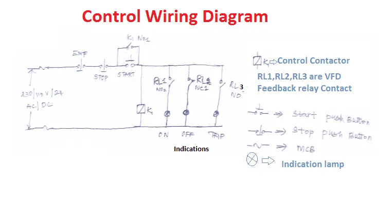
With motor running pilot light. Connect the gts to the dlc3. According to my wiring diagram, the headlight switch works a relay which is powered by two different fuses. The drawing for vfd start stop wiring diagram from panel.vfds are called as variable frequency drive or variable voltage variable frequency drive.
Choose which configuration you want to follow by looking at the diagrams provided below. No ac voltage in the cockpit. Neutral mains in to start/stop switch (23) neutral mains out from start/stop switch (24) to motor. Similarly, the in switch stop virtual contact will open any time someone presses the stop switch, thus stopping virtual power from flowing to the out contactor coil.
Mc motor starter wiring diagram with cb,mc,o/l, no, nc. I am here with giving you a vfd start stop wiring diagram for running a vfd through panel board push button and keypad of the vfd (it is called hmi). Starting system & wiring diagram amazon printed books www.createspace.com/3623931 amazon kindle edition. It's is a type of electric relay which can switch the 3 electric connections easily.
Power & control wiring trending. I've updated my wiring diagram, can you guys take a look please? For some robotics competitions, rc control is not allowed and the rover must be started in auto mode with an onboard switch. This is not part of the original datasheet.
Push/hold start switch in one convenient location and one or more mushroom stop switches as deemed beneficial. Grand vitara transfer position indicator does not come on at ignition switch on but engine stops. Used in indoor positioning, alarms, door switches, electronic meter. I will try to find the machine wiring diagram and post it here.
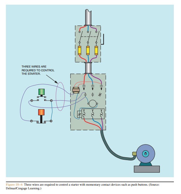
(physical switches wired to outputs devices, such as motor contactor and relays.) adding a jog input to the hard wiring diagram will look something like this: See image below for an example of 3 wire. Hello every one how to connection stop start with mini plc in circuit ? The symbol diagram is best but every one can't understand it easily that why i.
First off, i started by disassembling the safety switch. Inside, it just has two momentary switches, each with a normally open side and a normally closed side. The stop/start control of the ac drive can be achieved in a number of ways, mainly by controlling the start/stop input of the converter control circuit and. How to wire a key ignition and start stop switch to a diy simulator button box for a sim racing rig.
Typical dual circuit alternator wiring diagram. .wire the motor in a similar configuration: Most kenmore units have a wiring diagram/schematic glued to the back of the rear service panel, or folded and stored in the control head. I find millions of ladder diagrams, but no diagrams of physically wiring the switch.
There are 5 wires coming out of it, im trying to figure out which ones may be white is 12v+ input, [hot at all times] black/white is starter, [hot during cranking to start]. Wiring diagrams vs line diagrams. You can see that the diagram will work the exact same as the. For 3 phase induction motor start/stop we use always mc contact or.
Let's start with the basic stop stop circuit. Turn the power switch on (ig). In this video you can on,off device by switching the first click on switch device is. Float switch installation wiring and control diagrams.
The most common use of 3 wire control is a start/stop control. Pilot duty devices should not be used to switch horsepower or lighting loads unless they are. The mem starter also provided overload protection to the motor, the switch you have fitted only provides no volt protection so there is a risk of burning out the motor windings. Each part should be placed and connected with other.
Wiring a float switch isn't necessarily hard, but it can be a little confusing if you don't have a visual aid or two. Here is what it looks like hard wired. The way this function works is that an apm port is assigned to the start/stop switch and apm will wait for that pin to be brought low.
Gallery of Stop Start Switch Wiring Diagram

Download Schema Push On Start Stop Switch Wiring Diagram Full

Crabtree B15 3 Phase Stop Start Switch Model Engineer
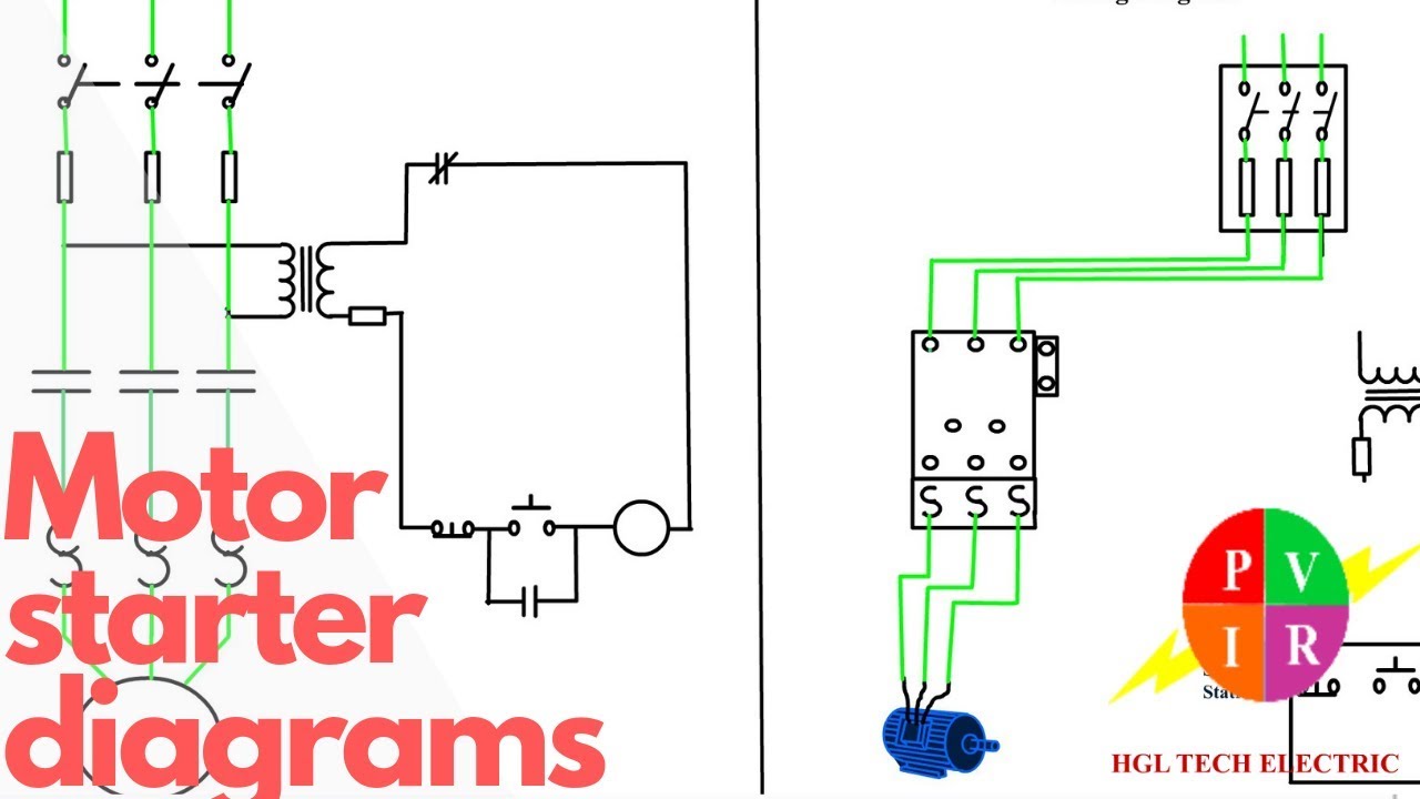
Diagram Slick Start Wiring Diagram Full Version Hd Quality

Practical Machinist Largest Manufacturing Technology Forum
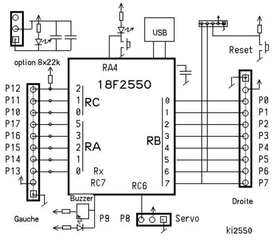
Diagram Stop Start Control Wiring Diagram Full Version Hd
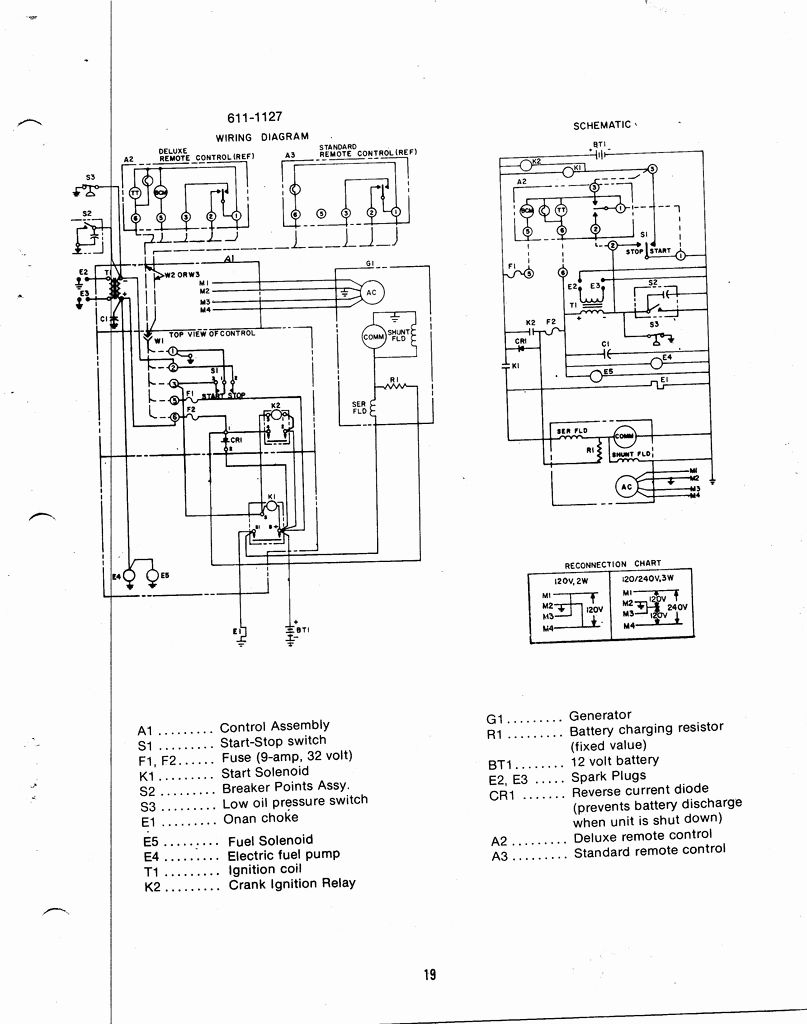
Diagram Key Switch Wiring Diagram For Onan B48m Full Version
Wiring Help Please Domino Start Kill Switch Honda Cbr
Basic Control Circuits Three Wire Control Circuits Electric
Two Wire Amp Three Wire Motor Control Circuit Motor Control
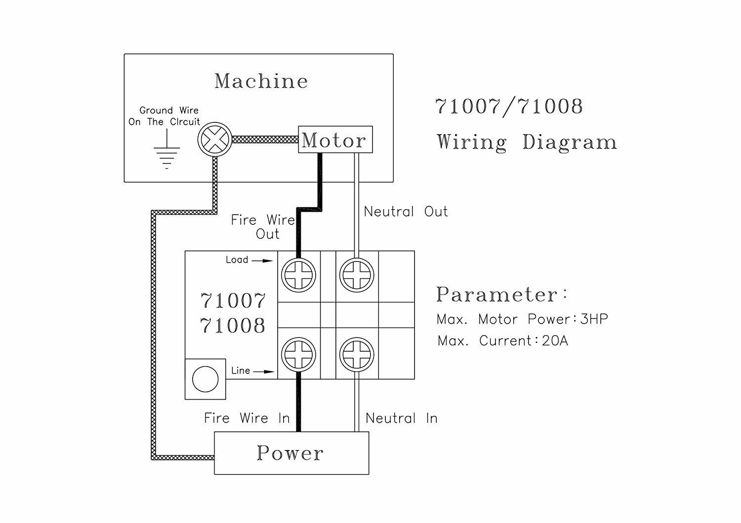
Business Amp Industrial On Off Switch Start Stop Powertec 71008

5 Wire Start Stop Diagram Full Version Hd Quality Stop
Vfd Start Stop Wiring Diagram Electrical4u

Wiring Diagram Single Motor With Start Stop Switch
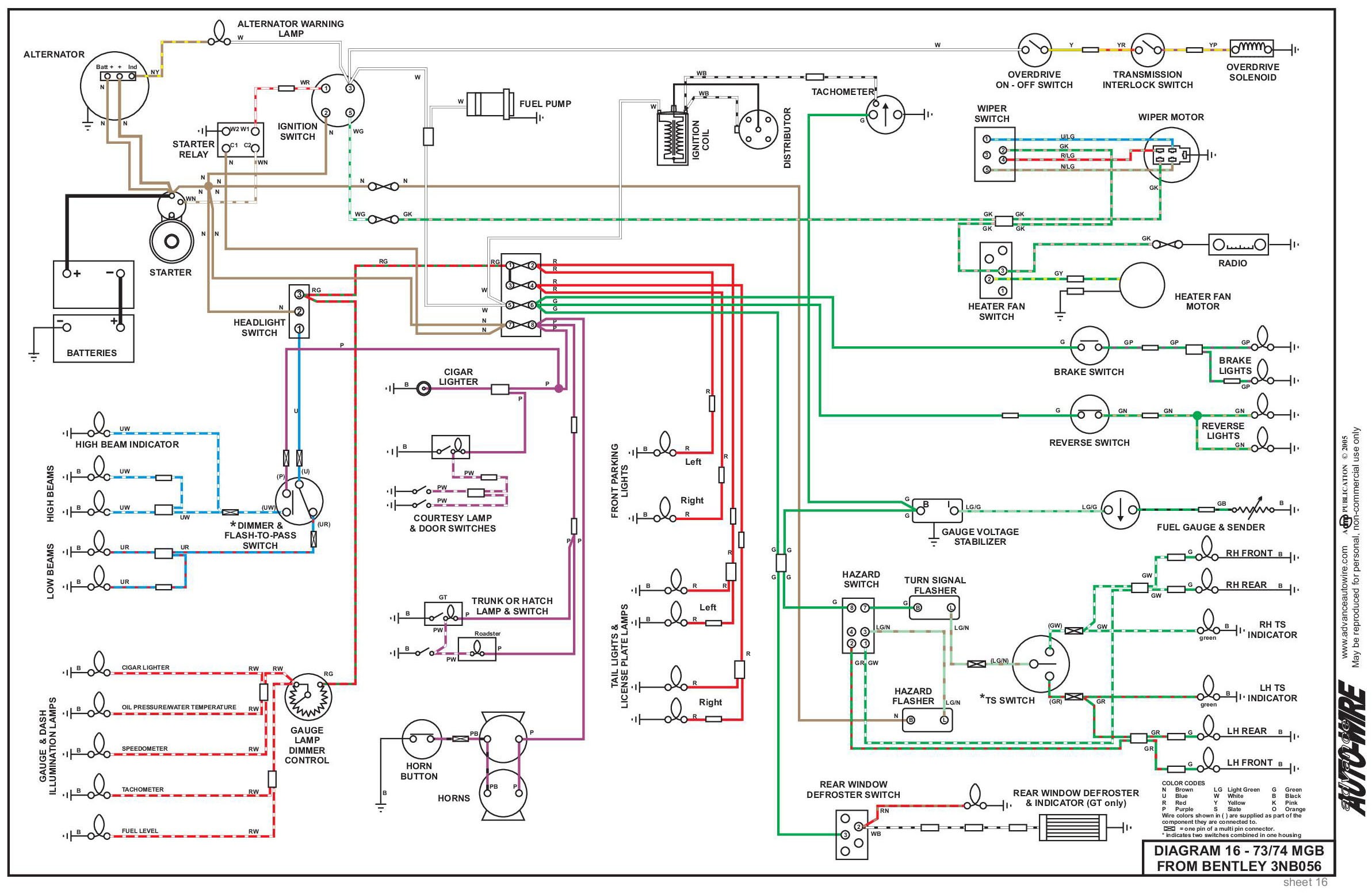
Diagram Emergency Stop Push Button Wiring Diagram Full

Unique Wiring Diagram For Emergency Stop Button Diagram
Starter Interrupt Relay Diagrams

Schematics And Wiring Diagrams Circuit 1
