Shear Diagram Triangular Load
Construction Business Amp Technology Conference Shear Wall Basics

Lecture 23 And 24
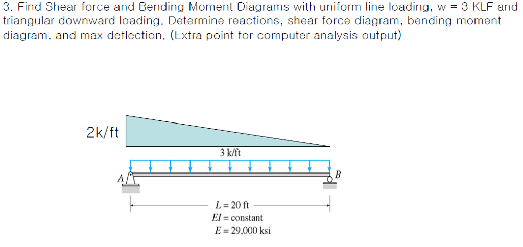
Solved Find Shear Force And Bending Moment Diagrams With
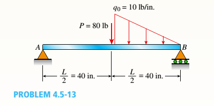
For maximum shear force to obtain we ought to multiply load and distance and it surely occurs at the.
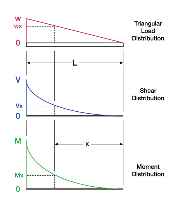
Shear diagram triangular load. What if there is more than one force, as shown in the diagram below, what would the shear force diagram look like finally, plot the points on the bending moment diagram. Deriving the shear force and bending moment equations for a beam with a triangular load. A triangular or trapezoidal load distribution will result in a parabolic shape between the two ends on the shear force diagram (because in integral of a line by the time the shear force diagram reaches the end of the beam at point d (and there are no additional loads to consider at point d for this example). Trapezoid is generally form with the combination of uniformly.
I've been attempting this fundamental shear force diagram problem for several days, but can't seem to get the correct result. Each axis is divided into 100, representing percentages. To complete a shear force and bending moment diagram neatly you will need the following materials. Shear force and bending moment diagrams.
As shown in the diagram trapezoidal load is that which is acting on the span length in the form of trapezoid. Method of sections 28 moving on, the video introduces with the triangular distributed loads and briefly demonstrates how to convert a triangular distributed load into a point load. As we need to convert the udl in to load, we multiply the length of the cantilever beam with udl acting upon. Determine the normal and shearing stresses 2.6 (b) represents the free body diagram of a triangular element separated from the block by a plane.
- 2004 Ford Expedition Fuse Box Diagram
- Belt Diagram John Deere L120
- John Deere La105 Drive Belt Diagram
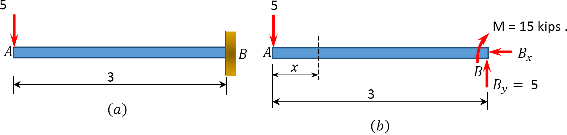
Cantilever beam calculation carrying a triangular and a concentrated load. This video shows how to solve beam with triangular load. The shear diagram is an integration of the loading diagram, and the moment diagram is an integration of the shear diagram. Introduction to axial & shear forces and bending moments 26:
To construct a shear diagram. I'm experiencing a difficulty understanding how the trapezoidal loads are distributed and how to shear moment diagrams are drawn for structural members subjected to trapezoidal loading. Both curves are in the 2 nd deg. The moment diagram is a straight, sloped line for distances.
Calculate the deflection of steel, wood and other materials. This article will discuss the steps for drawing. In this video triangular load has been calculated, shear force diagram and bending moment diagram. In this video triangular load has been calculated, shear force diagram and bending moment diagram.
Axial, shear and bending diagrams 27: The shear diagram from b to c is a parabola, thus, the moment diagram of segment bc is a third degree curve. A simply supported beam has a triangular load distribution applied as shown. Since the segment is chosen at a point x where there is no concentrated forces or moments, the result of this analysis will not apply to points of concentrated the slope of the shear diagram at a point is equal to the intensity of the distributed loading w(x) at that point.
Bendingmomentdiagram.com is a free online calculator that generates bending moment diagrams (bmd) and shear force diagrams (sfd) for most simple beams. We had a tutorial similar before but this. 1) under the first load diagram, drop vertical lines at every concentrated load, at every 5) you can tell if a triangular load diagram should turn into a skinny parabola or a fat parabola by using the calculus: A cantilever beam with a uniformly distributed load on its span.
A menu appears above the graph offering several options, including downloading an. Click the 'calculate' followed by 'create triangular graph' buttons and your triangular graph will open in a new window. Join all the points up, except those that are under the uniformly distributed load (udl). This video is part of the 'shear moment diagram.
It will work for all simply supported, determinant beams and is capable of taking point loads, concentrated moments and distributed loads. Basic shear diagram[edit | edit source]. And i found the area under the load curve, it's just a triangular area. Therefore, the distributed load q(x) is statically equivalent to a concentrated load of magnitude q placed example 1.
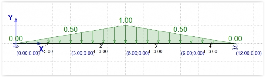
Shear and bending moment diagrams are analytical tools used in conjunction with structural analysis to help perform structural design by determining the value of shear force and bending moment at a given point of a structural element such as a beam. The distributed loads can be arranged so that they are uniformly distributed loads (udl), triangular distributed loads or trapezoidal distributed loads. Shear force and bending moment diagrams. Triangular load is that whose magnitude is zero at one end of span and increases constantly till the 2nd end of the span.
In this second shear and moment diagram video, i show how to calculate shear and moment diagrams for a variety of loading. One shear and moment diagram, coming up! Shear force diagram, shear force equation and bending diagram are very important from design point of view. The value at any point on any diagram turns into.
I'm trying to calculate the after reading multiple textbooks and watching several videos, i finally found out that if the maximum load of a triangular load distribution is at the initial. Normal stresses produced due to axial loading or shearing stresses caused due to shearing force compressive forces of 60 kn at each and of the bar. Relations between distributed loads and internal shear forces and bending moments. Define and calculate shear force in a beam, draw and calculate bending moment in a beam.
Gallery of Shear Diagram Triangular Load
Stressing Structure
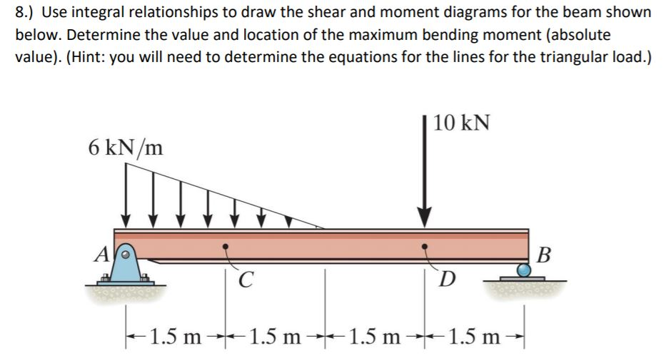
Solved 8 Use Integral Relationships To Draw The Shear A

Sfd Amp Bmd Shear Force Amp Bending Moment Diagram
Sfd Amp Bmd Shear Force Amp Bending Moment Diagram
Calculation Example Member Diagram Triangular Load

Solved The Cantilever Beam In Fig Carries A Triangular
Solution To Problem 410 Shear And Moment Diagrams Mathalino

Shear And Moment Diagrams S B A Invent In This Moment

The Simple Beam Ab Supports A Triangular Load Of Maximum
Chapter 4 Internal Forces In Beams And Frames In
The Simple Beam Ab Supports A Triangular Load Of Maximum
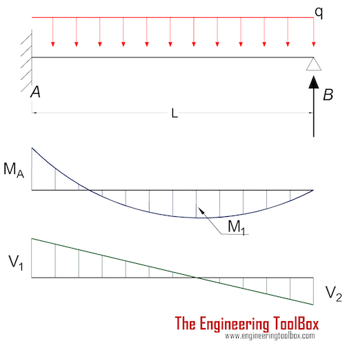
Beams Fixed At One End And Supported At The Other

Draw The Shear And Moment Diagrams For The Beam Docsity

What Are Steps To Convert A Shear Force Diagram Into A Load
4 Internal Forces In Beams And Frames Engineering Libretexts
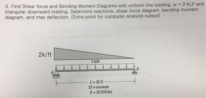
Get Answer Find Shear Force And Bending Moment Diagrams
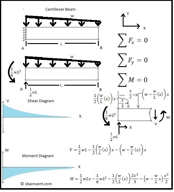
Shear And Moment Diagrams S B A Invent
