Shear And Moment Diagram For Triangular Distributed Load

Pin On Figaw
Cantilever Beams Moments And Deflections

Part A Draw The Moment Diagram For The Beam Follow The Sign
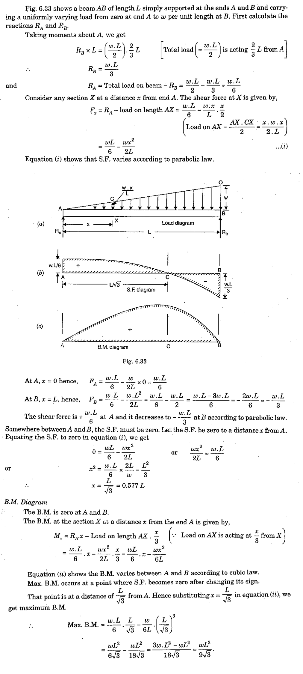
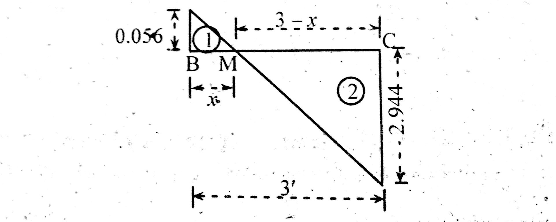
The total distribute load on and on each of which act through their centres of gravity.
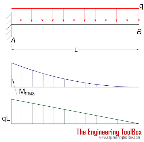
Shear and moment diagram for triangular distributed load. Calculate the deflection of steel, wood and other materials. Write shear and moment equations for the beams in the following problems. 5 uniformly distributed load (udl). This video shows how to solve beam with triangular load.
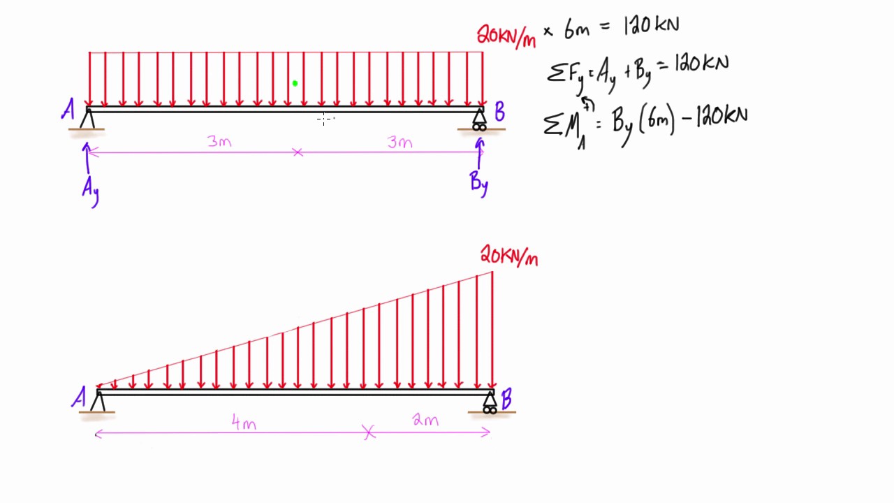
14 solve it draw the shear and moment diagrams for simply supported beam. The distributed load can be split into two parts, a rectangular and triangular shape. The intensity of the load varies from 1.0 kn/m at support a. • for a triangular distributed load, the magnitude of the resultant force is the area of the triangle, ½*b.
Cantilever beam calculation carrying a triangular and a concentrated load. Homework statement for the overhanging beam in the figure, a) draw the moment diagram indicating all critical values including the maximum moment homework equations. We had a tutorial similar before but this. Moment diagram shear diagram shear and moment diagrams cantilever beam triangular load uniformly varying load.
- 2007 Nissan Titan Fuse Box Diagram
- 2005 Chevy Silverado Speaker Wiring Diagram
- Harley Sportster Parts Diagram
To be truly ignorant, be 1. Equivalent systems, distributed loads, centers of mass, and centroids. Finally, plot the points on the bending moment diagram. • a load applied across a length or area instead of at one point.
Join all the points up, except those that are under the uniformly distributed load (udl), which are points b,c and d. To construct a moment diagram. Constructing shear and moment diagrams areas and 3) if you cross a distributed load going down, the magnitude under that distributed load (it's area) will 5) you can tell if a triangular load diagram should turn into a skinny parabola or a fat parabola by. As seen below, you need to draw a curve.
To complete a shear force and bending moment diagram neatly you will need the following materials. Also, draw shear and moment diagrams, specifying values at all change of loading positions and at points of zero shear. Displayà show load assign à frame/cable/tendon on the pop up window click make sure that show joint loads with span loads and show span loading values are selected then press ok. Bending moment diagram example 56:
Shear and moment diagrams and formulas are excerpted from the western woods use book, 4th edition, and are provided herein as a courtesy of western wood products association. In this video triangular load has been calculated, shear force diagram and bending moment diagram. Since the segment is chosen at a point x where there is no concentrated forces or moments, the result of this analysis will not apply to points of the slope of the shear diagram at a point is equal to the intensity of the distributed loading w(x) at that point. Draw the shear and bending moment diagram for.
What is a distributed load? Problem 417 beam carrying the triangular loading shown in fig. Use the same commands as shown, but with the following changes: Uniformly varying load is distributed over the entire span or part of the span in such a way that the intensity of the load gradually increases from zero to maximum.
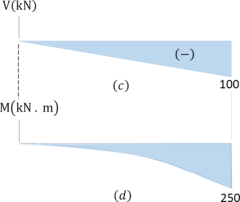
Problem 411 cantilever beam carrying a distributed load with intensity varying from wo at the free end to zero at the wall, as shown in fig. In this second shear and moment diagram video, i show how to calculate shear and moment diagrams for a variety of loading. For the distributed load to show select: The complete diagrams are shown.
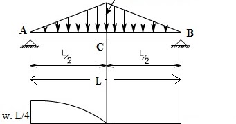
These are from a and from c in the other case. Note that the intensity of the triangular load at the section is found by proportion, that is, w>x = w0>l or w. Shear and bending the objectives of this tutorial video are to discuss about different distributed loads combinations the triangular distributed loads and briefly demonstrates how to convert a triangular distributed load. A c b 4 ft 6 ft 4 ft 4 ft 331 06 solutions 46060_part1 the intensity of the triangular distributed load at the point of sectioning is w = 150 a b = 12.5x x 12 referring to fig.
Define and calculate shear force in a beam, draw and calculate bending moment in a beam. The purpose of determining the support reaction forces r1 and r2, the distributed triangular load can be 2. The distributed loads can be arranged so that they are uniformly distributed loads (udl), triangular distributed loads or trapezoidal distributed loads. Load shear diagram • construct moment diagram.
Structural analysis of statically determinate beams. Shear and bending moment diagrams are analytical tools used in conjunction with structural analysis to help perform structural design by determining the value of shear force and bending moment at a given point of a structural element such as a beam. .shear force diagram example 55: Draw the shear and moment diagrams for the beam shown in fig.
Plot shear and moment diagrams the functions for v and m for both beam sections can be plotted to give the shear and moment over the length of the beam. Draw the shear and moment diagrams for the 6 kip 8 kip compound beam which is pin connected at b. My understanding of triangular load distribution in terms of the intensity $w(x)$ is that after reading multiple textbooks and watching several videos, i finally found out that if the maximum load of a triangular load distribution is at the initial point $x=0$ then the following formula should be applied • a distributed load can be equated with a concentrated load applied at a specific point along the bar.
Keep in mind that we have already derived the proper location for a force caused by a triangular load distribution. B, 1 + c ©fy = 0; For the second the purpose of the tutorial was to show how to find shear and bending moment diagrams in ansys, so that the process could then be applied to more complex. Deriving the shear force and bending moment equations for a beam with a triangular load.
Gallery of Shear And Moment Diagram For Triangular Distributed Load

How To Calculate And Draw Shear And Bending Moment Diagrams
How To Calculate The Zero Shear Point From A Parabolic Shear

Pin On Civil Engineering

Tc 7411 And Moment Diagrams Solution To Problem 408 Shear
Shear Force And Bending Moment Diagram For Simply Supported Beam

Solution To Problem 411 Shear And Moment Diagrams Mathalino
4 Internal Forces In Beams And Frames Engineering Libretexts

A Cantilever Under Linear Distributed Load The Shear Force

Bending Moment Diagram An Overview Sciencedirect Topics
Shear Force And Bending Moment Diagrams For A Simply
De 12 Lesson 19 Solved Examples Based On Shear Force And
How To Locate Point Of Zero Shear Maximum Bending Moment

For The Beam With Loading Shown Below Determine The
Distributed Loading On A Beam Example 2 Triangular Loads

Shear Force Amp Bending Moment With Triangular Load On Beam

1 Match The Following Distributed Loads With The Proper
Problem 736 Shear And Moment Diagrams Of Fully Restrained
