Rpm Sensor Wiring Diagram

Pin On Projekter Jeg Vil Prove

Troubleshooting Boat Gauges And Meters Boatus Magazine

Diagram Volvo S40 Wiring Diagram Schematic Full Version Hd
Digital tachometer using ir sensor with arduino for measuring rpm.
Rpm sensor wiring diagram. This is commonly done using a standard servo plug. Design active sensor, consisting of a housing with integral evaluation circuit and a sensor element which is based on the hall principle. Collect all useful circuits for you. Our sensor range includes pressure sensors and switches, and temperature sensors and switches, as well as speed, rpm and rotational sensors and position sensors.
• refer to vehicle service manual for oxygen sensor wiring diagram. (1) is fixed to the cylinder block/crankcase and is facing the flywheel on the crankshaft pulley. The wires should be connected in the following manner to arduino : Wire 1 and wire 2 are connected to wires from esc to motor.
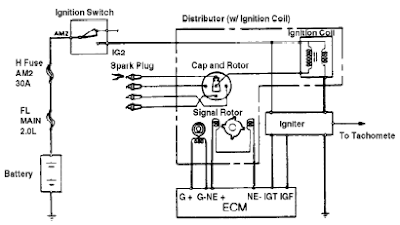
The crankshaft position sensor gives a report on engine rpm and this is how the fuel pressure is set for a given rpm. The cold start sequence could temporarily enrichen the fuel and adjust rpm then hand off duties to position sensors. Typically this sees the reported rpm at 1100 rpm jump to 5000+ rpm for short periods. You can use hall effect sensor to make many diy projects such as rpm meter, magnet detector, and more project involves with a magnet.
Source code/program & circuit diagram given. If you'd like to get started with this type of sensing, t. 1971 porsche 911 relay switch fuse box diagram 1971 porsche 911 relay switch fuse box map fuse panel layout diagram… Maf sensor multimeter diagnostic test.
All gauges come complete with wiring harness and associated sensor. From here, you can infer the distance that your device has traveled, or any number of other important variables. This optional sensor adapter harness for stack st700 displays allows for connection of a combination of two analog pressure or. Ardupilot supports the use of numerous types of rpm sensors.
Primary hall sensor wiring diagram. You can attach it easily to the master display console to count the rpm. Mass air flow (maf) sensors. Rpm adapter, allows use of st670 (not included) as engine rpm sensor.
Block diagrams of the kmi 15/x and kmi 16/x rotational speed sensors with integrated signal conditioning. They are commonly used in the three wires should then be plugged into autopilot. And powered it up with a 12v/500ma regulated power supply unit. Operating principle the sensor consists of a tubular casing (1) containing a permanent magnet (3) and an electrical.
Engine rpm and tdc sensor, wiring connector. Up to 4 rpms can be measured in this way (with connecting the sensor to your power system. Note that the external wiring diagram in this sensors and wiring section is entirely separate from, though similar to, the relay board. A sensor is essential to sense shaft speed.
Knock sensor signal gain should be adjusted so that the knock sensor value parameter doesn't exceed 3v across the full rpm range during normal combustion. Task produce a square wave signal from the sbc control unit (a7/3n1). It detects the voltage changes at the wires of brushless motor, and then outputs the rpm signal. Proximity sensors provide medium (or low) resolution sensing, depending on the number of pulses measured per revolution.
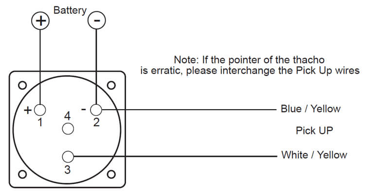
For a quick test, i prepared the kit as shown in the below wiring diagram: Use this simple, clear car dashboard diagram with labels and warning light symbols to better understand what's what. If polarity is reversed, triggering will be erratic or may not occur at all. Please be sure to read the instruction manual for the the rev speed meter requires both the instruction manual and the wiring diagram for proper even though a vehicle is listed in this manual.
Rpm sensor】 the rpm sensor is an accessory of the high voltage speed controller. This sensor sends a signal to the. This experiment requires very specific attention to the proximity between the neodymium below is the wiring diagram for the a3144 hall sensor and the blower to the arduino uno board How the rpm sensor library works.
Fuzzy logic controller pid diagram text: Arduino due has 3.3v current algorithm and code gives reasonable accuracy of around 10 rpm and update speed of. Vr sensors have two wires (and often a 3rd (shield)). Sensor measuring a motor's rpm may be called a special feature of the nlx220 is the.
Q , is inadvertently wired backwards, the sensor will not be damaged. Black wire is connected to 5vcc and the problem is with the wiring. 1.4 comments hall effect sensor uses analog 0, 16x2 lcd uses digital 7, 8, 9, 10, 11, 12. The wires of the sensor are designed to carry only the tiny currents required for the sensor to.
Hall effect sensor (hes) works on the principle of interaction of magnetic field with electrons flowing in step 2: Rpm readings are used in the automotive, aerospace, and manufacturing fields. This rpm sensor can work with some speed control systems for helicopters. The polarity must be known.
1 hall effect rpm counter. When dealing with robotics and other electronics projects, it can be important to know how many revolutions a motor is making. The pinout of our rpm sensor( which uses. For a free wiring diagram please visit the website below.
Rpm sensor datasheet, cross reference, circuit and application notes in pdf format. The brushless sensor can also be used as a secondary rpm sensor with your recorder. The left rear rpm sensor and right rear rpm sensor are mounted on the rear axle wheel carrier.
Gallery of Rpm Sensor Wiring Diagram

Om 9211 Garage Door Safety Sensor Wiring Furthermore Garage

Digital Rpm Counter Intro
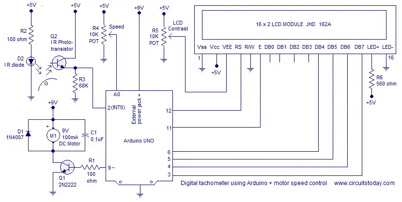
Digital Tachometer Using Arduino Plus Motor Speed Control

Draw Your Wiring Rpm Schematic Diagram
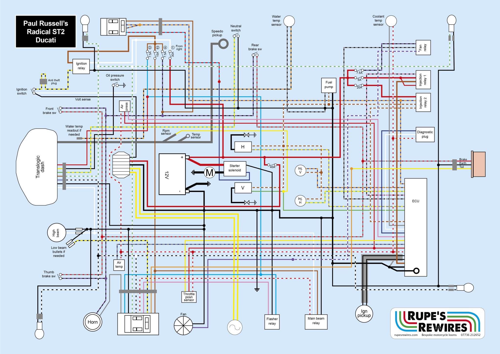
Diagram Ducati St2 Wiring Diagram Full Version Hd Quality
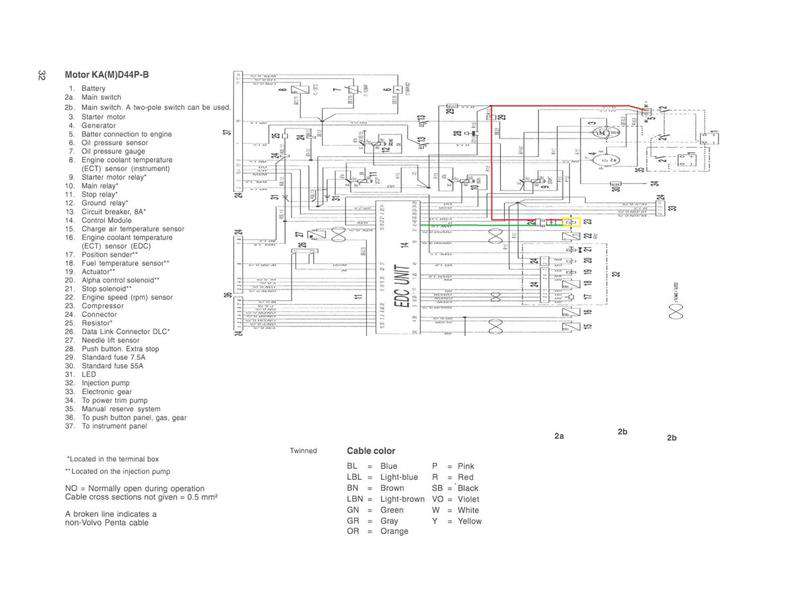
Diagram Volvo Penta Kad 44 Wiring Diagram Full Version Hd
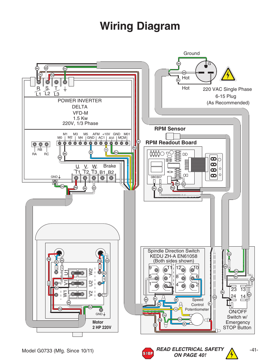
Diagram 2 Phase Electrical Wiring Diagram Full Version Hd
Digital Led Rpm Speedometer Tachometer With Hall Senzor
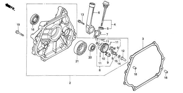
Diagram Motorcycle Rpm Wiring Diagram Full Version Hd

Electronic Power Steering Knowyou Parts
Aviasport Rotax 912 Tachometer 2 1 4 In
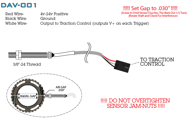
Drive Shaft Rpm Rings Amp Sensors Davis Technologies

Diagram Torque Rpm Diagram Full Version Hd Quality Rpm
Fzj80 To Hzj80 Conversion Tach Wiring Problem Ih8mud Forum
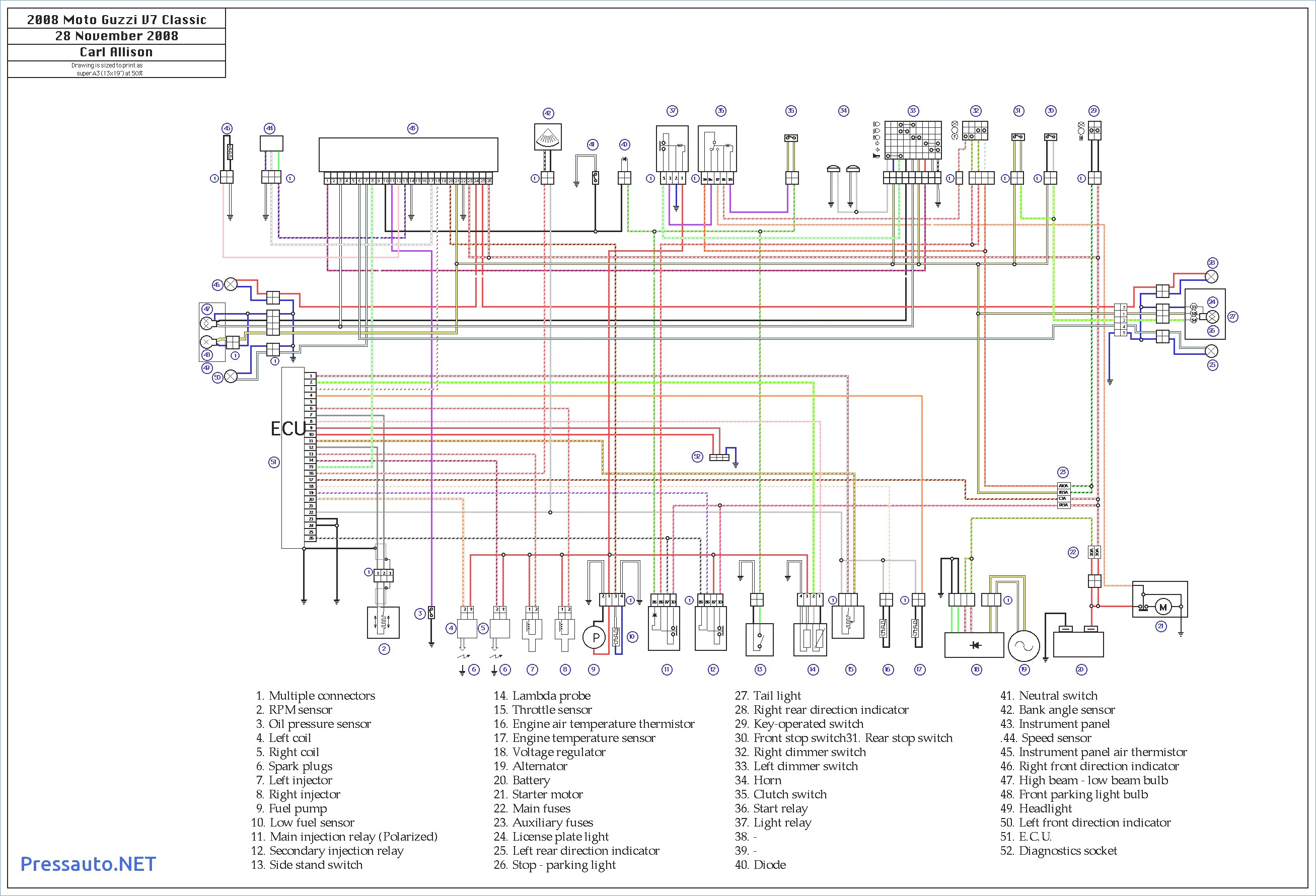
Diagram Yamaha Warrior Ignition Switch Wiring Diagram Full
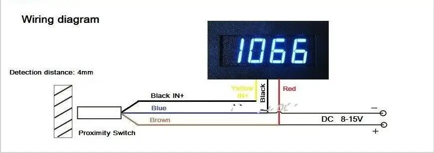
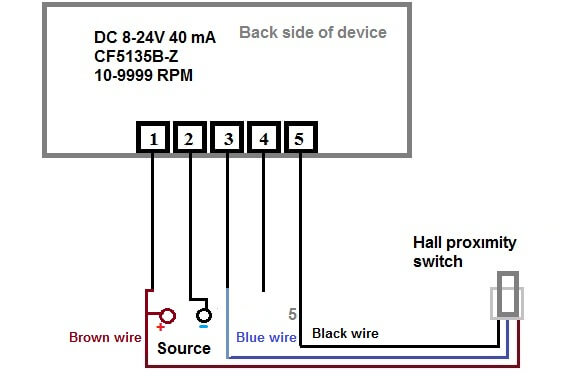
New Blue Led Tachometer Rpm Speed Meter Proximity Switch Sensor Npn 3 Wire
Autotronics Studies 2010
