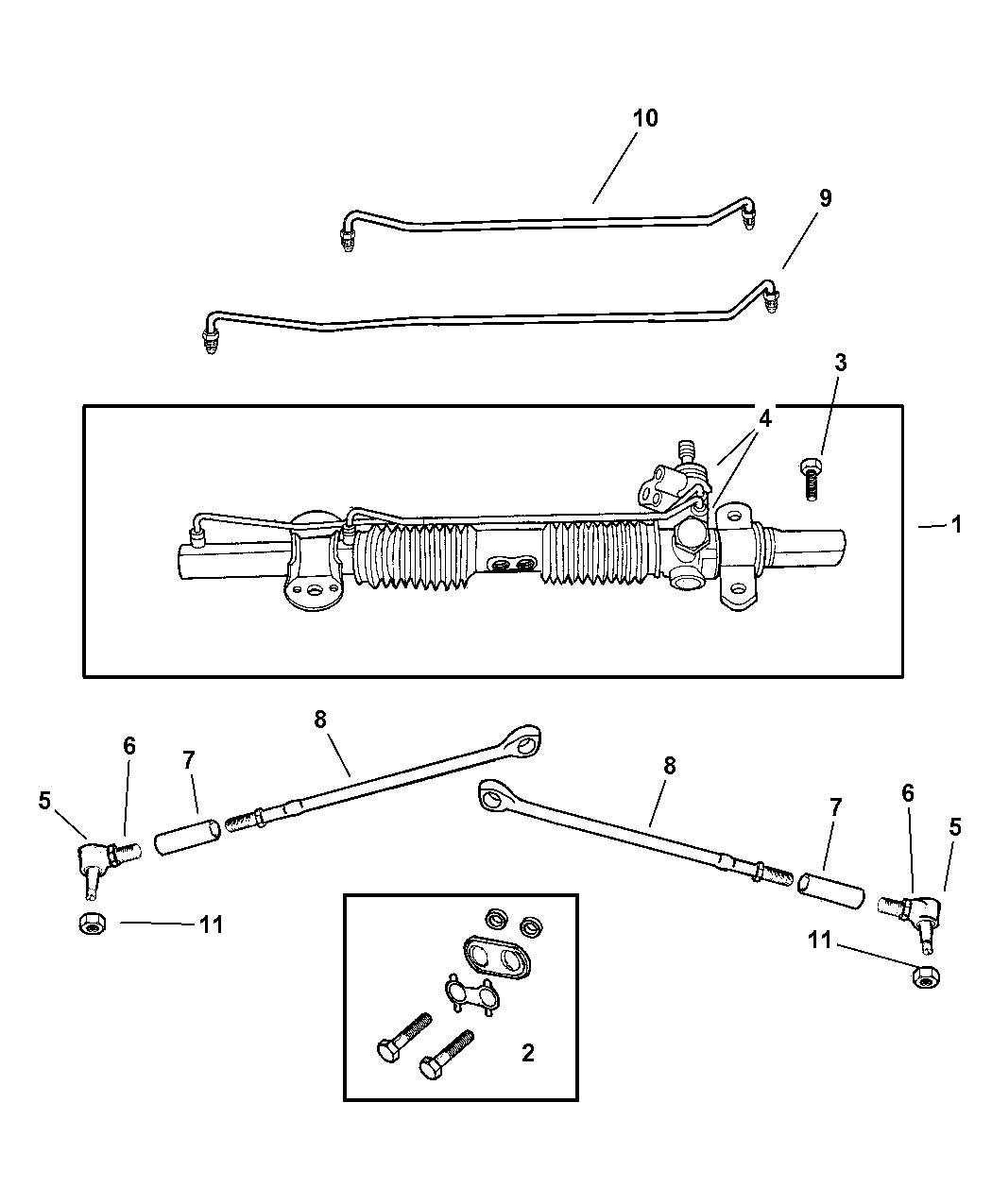
Rack And Pinion Parts Diagram
The rack and pinion system is both simpler and more complex than the parallelogram system.
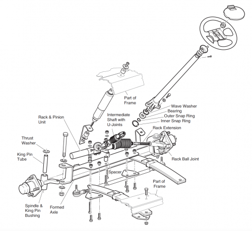
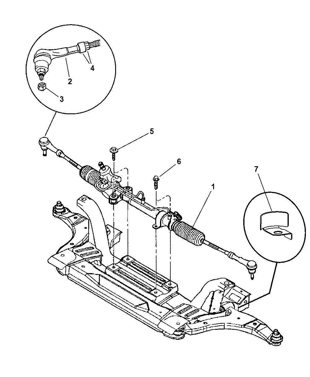
Rack and pinion parts diagram. The chances are your car has rack and pinion steering. Learn the ins and outs of solidworks' rack and pinion mate. Rack and pinion is a modern steering mechanism that is used on most if not all vehicles in todays models. Rack and pinion mechanical parts.
Automotive steering system infographic diagram showing both types parallelogram and rack and pinion with all parts cogwheel with rack pinion multi colored flat icons on plain square backgrounds. Documents similar to rack and pinion mechanical parts. Rack and pinion is a generic term for a pair of gears which convert linear motion into rotational motion. Discover more about your rack and pinion steering system:
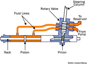
A rack and pinion is a type of linear actuator that comprises a circular gear (the pinion) engaging a linear gear (the rack), which operate to translate rotational motion into linear motion. The gear appears to bounce back. Rack and pinion gears are used to convert rotation into linear motion. Rotational motion applied to the pinion causes the rack to move.
- John Deere Lx188 Carburetor Diagram
- Honda Harmony 1011 Belt Routing
- 20a 250v Receptacle Wiring Diagram
Telescope parts diagram bushnell north star 78 7876 user manual save rack and pinion diagram to get e mail alerts and updates. Since there isn't a rack and pinion automated gear design tool in inventor, this is the gear every inventor user is looking for. View 33 best rack and pinion diagram images. The gear system is marked a and b.
Download files and build them with your 3d printer, laser cutter, or cnc. Included white and darker icon variations for hover or active effects. The way this tolerance is derived will be appreciated from the diagram below. Complete the enlarged diagram of a rack and pinion, by drawing the rack in a vertical position, as it would be on a drilling machine.
A rack and pinion mechanism can generate a linear motion, which can be adapted into a variety of whimsical craft ideas. It's simpler because there are fewer components involved that we can see: These internal parts are the rack and pinion themselves, and two outer tie rods. Names for parts a and b ?
Related searches for rack and pinion diagram: This is a mechanism for converting rotary motion to linear oscillating motion. Learn how to create an automated geared mechanism with hypnotic motion. Pneumatic actuators, in comparison to their electric counter parts, are generally more durable, better suited for hazardous environments and.
It's been an incredibly popular engineering choice for years, but have you ever stopped to ponder exactly how it works? The values given in the load table are based upon uniform, smooth operation, khß=1.0 and reliable grease lubrication. Since, in practice, the applications are very diverse, it is important to consider the given conditions by using. The rod & custom kit converts your mustang to rack and pinion steering with disc brakes and removes the shock towers from your engine bay.
All credits for the srivastava brothers The pinion blank after 90° and 360° of cutting motion is shown in figure 10(b) and (c), respectively, whereas its mesh with the rack is shown in figure 10 later on, tooth profile error is introduced in the gear pair by removing part of involute surface from one of the gears making one tooth surface as flat. Automotive steering system infographic diagram showing both types parallelogram and rack and pinion with all parts for mechanics and road traffic safety science education. The resulting undesirable relative movement between wheels and steering gear cause unintended steering.
You'll see how to make a standard rack and pinion, but also other cool ways to use this mate. Inverter circuit diagram led driver circuit diagram electric toy car wiring diagram schematic diagram refrigerator circuit diagram inverter circuit there are 1 suppliers who sells rack and pinion diagram on alibaba.com, mainly located in asia. This 1966 mustang fastback is one of the restorations we recently finished here at cj's. Driving the pinion into rotation causes the rack to be driven linearly.
A rack and pinion is a type of linear actuator that comprises a pair of gears which convert rotational motion into linear motion. I also show how a motion link can simulate. A piston coaxial to the rack provides hydraulic assistance force, and an open centered rotary valve controls the assist level. 1920 rack and pinion 3d models.
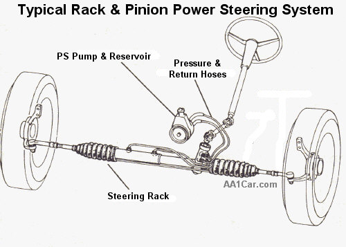
Rack and pinion steering is an incredibly popular setup in modern vehicles, but how does it actually work? Build a simple linear mechanical movement and apply into your own kinetic craft. Thingiverse is a universe of things. The steering rack and two tie rod ends.
Features such as high reliability and repeatability ensure that rack and pinion systems are the first choice for linear and angular 1. A circular gear called the pinion engages teeth on a linear gear bar called the rack; Use the adafruit crickit and circuit playground express to make it dance! Protected rack channel & pinion shaft encoder typical system accuracy ±0.010 mm.
The efficiency η of meshing between pinion and rack is fully active only if the transmitted power is greater than the power threshold. The flat, toothed part is the rack and the gear is the pinion. Every day new 3d models from all over the world.


