Quicksilver Throttle Wiring Diagram
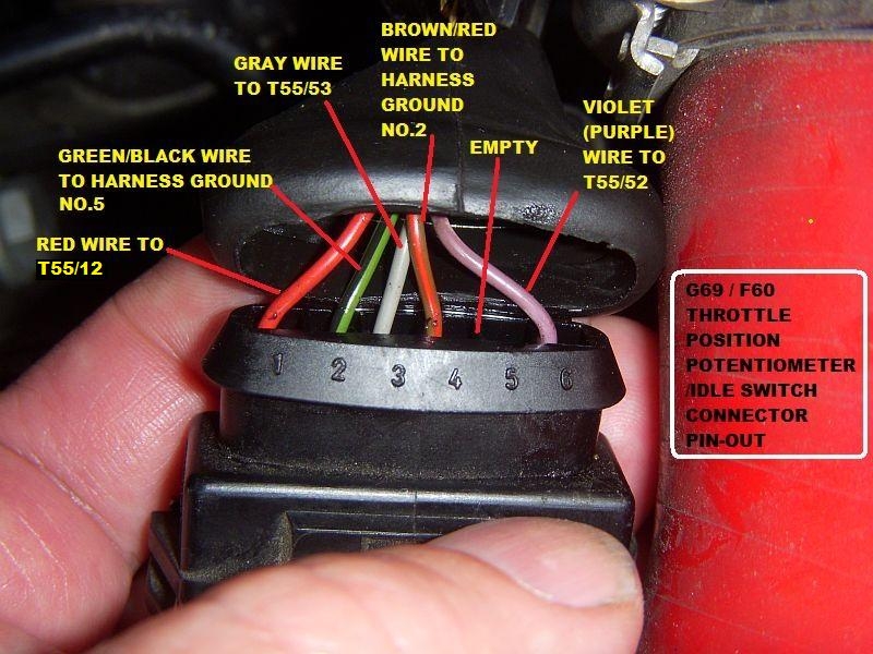
Diagram Quicksilver Throttle Wiring Diagram Full Version Hd
Quicksilver 3000 Throttle Manual
Schema 12 Pin Wiring Diagram Mercury Full Version Hd Quality
The system bmw use is referred to as eml (german term for electronic throttle control).
Quicksilver throttle wiring diagram. It does not matter if the tps signal is rising or falling when the throttle is opened, during calibration this will be sorted. Mercury/quicksilver parts 8m0011213 remote control remote control panel mount. The basic and identification colours are abbreviated using the international norm iec 757. The hall sensor throttle requires three wires to operate.
Cutqut witch, (al connect leads with saw and nut; Unsure if the orange common wire that is shown attached to the capacitor is what's supposed to be spliced with the yellow wire coming out of the new motor. Primary remote throttle with one or more secondary remote throttles. A splice of a brown with black stripe, wire size being 0.8 square millimeters (18 gauge awg).
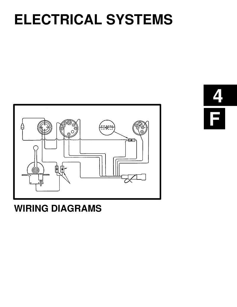
In the wiring diagrams the wire colours will be located separately next to the wires as before. I need to replace the wiring ribbon which comes with the something with the right amount of wires and. Insulate with neoaene.or ibi connect to neutral. I hope your not trying to extend the wiring for the throttle by wire.
- 1999 Dodge Dakota Wiring Schematic
- 2007 Gmc Yukon Stereo Wiring Diagram
- New Style 13 Speed Shift Knob Air Line Diagram
Have lost diagram after salvage of houseboat. It provides for direction, throttle and momentum control, along with an emergency stop feature. Remote throttle connector/cable pin wire color description 1 red supply voltage 2 black ground 3 oragne n/c 4 white n/c 5 green n/c 6 yellow eta400 rev150618. This is the model with the gear shift combined with the throttle.
The wiring diagram is available in the service manual. The details of the sensor and how the motors work i don't think anyone here knows. On the examples below or any other diagram, be sure and notice which side of the connector you are. Some have made references to removing the square button and removing a 11/16 nut.
I have a thrustmaster warthog hotas which has a broken wire running from the throttle metal pinkie switch and auto pilot button to the board. The diagram shows a combined gps and compass. 22.04.2020 · quicksilver mander 2000 wiring diagram car quicksliver throttle shifter wiring diagram and mercury quicksilver shift. A box drawn with a solid line in a wiring diagram indicates _.
Wiring up a wheelchair motor to a dc speed controller is a little bit different because of the electronic brake attached to the back of the motor. Hey there ron.i need a replacement handle for that same quicksilver throttle control on your (1985 celebrity calais, mercruiser 3.7l 170hp) if you or anyone. Ifremote control is not equipped with throttle position. A simple multimeter will suffice and in this article i'll take you thru' the whole diagnostic process step by step.
On a wiring diagram, s110 with a .8 brn/blk means _. Throttle position sensor (tps) wiring diagram (part 1). The throttle cable has almost become redundant on today's motor vehicle. Does anyone have a wiring diagram for the tbw connector in the bars?
There is an separate internal wiring diagram for the relay board. You don't even need a scan tool to test it. The throttle controller is a quicksilver na1601 and all the plastic bushing have broken. Refer to the engine specific wiring diagram for the.
Manufactures high performance, cost effective motion control products for use in the original equipment manufacturer market. Mercury throttle control removal, mercury throttle diagram, mercury smartcraft throttle manual, mercury throttle control handle. The relay board takes 12v from the vehicle and passes it to the megasquirt® efi controller, but it also handles fuel pump relay and the throttle position sensor is used for flood clear mode and ego enrichment, as well as accel enrichment I'm looking for a wiring diagram for a mercury 75 hp 4 stroke s/n:0g982237 production year 2007 thank you.
Testing and troubleshooting the throttle position sensor (tps) on your ford or lincoln car, pick up or suv is an easy thing to do. If you are the throttle won't work. The throttle position sensor must be wired up according to the diagram below. Pushed the throttle botton and moved the handle completely forward.
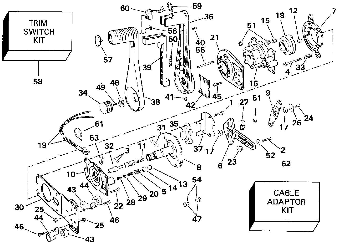
Hoping pictures will help avoid misunderstandings. In this video i remove the quicksilver commander 4000 pistol throttle from my boat, disassemble it and identify some areas causing a significant amount of. Here's a brief description of the throttle position sensor (tps). The gps/compass should be mounted on the frame as far away from other electronics as possible, with the direction marker towards the front of the vehicle (separating the compass from other electronics will reduce interference).
Maybe in the electrical forum. Quicksilver has seven wires red.
Gallery of Quicksilver Throttle Wiring Diagram

Diagram Mercury Outboard Control Wiring Diagram Full Version

Diagram Mercury Quicksilver Wiring Diagram Full Version Hd
Diagram In Pictures Database Mercury Quicksilver Control

Diagram Mercury Quicksilver Control Wiring Diagram Full

Quicksilver Gauge Wiring Diagram 1976 Chevy Corvette Wiring
701feb Quicksilver Throttle Control Wiring Diagram Wiring

Diagram In Pictures Database Mercury Quicksilver Wiring

Diagram Wiring Diagram For Boat Trim Solenoids Full Version

Quicksilver Commander 2000 Manual

Quicksilver 3000 Throttle Removal Amp Installation Ranger Bass Boat

Diagram Quicksilver Throttle Wiring Diagram Full Version Hd

Diagram Quicksilver Throttle Wiring Diagram Full Version Hd
Mercruiser Electrical Diagrams Engines Drives And

All Download Quicksilver Throttle Control Wiring Diagram

Remote Control Assembly 3000 Classic 2000 Quicksilver

Quicksilver Side Mount Remote Control 8 Pin Traditional W 15 Harness
Diagram Quicksilver Throttle Control Wiring Diagram Full
