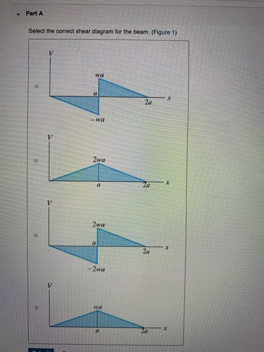
Select The Correct Shear Diagram For The Beam

Diagram Tree Shear Wiring Diagram Full Version Hd Quality
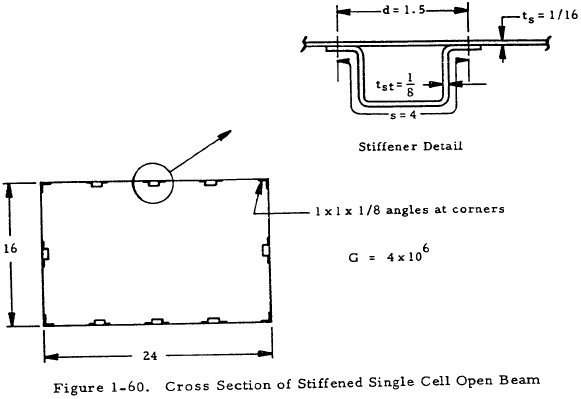
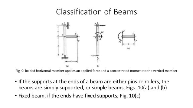
Beam Torsion Engineering Library

Structural Design For Non Structural Engineers
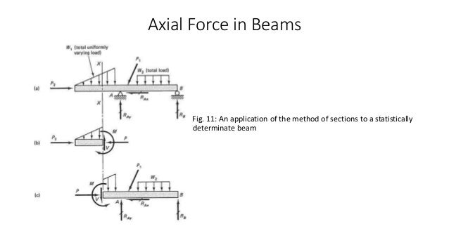
Resistance to bending and shear force is given more importance than resistance to normal force in most cases involving beams.
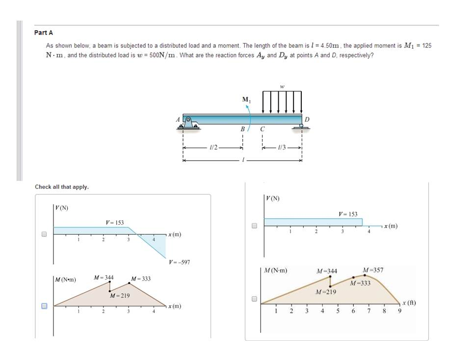
Select the correct shear diagram for the beam. For your reference, this problem (f11.6) can be found in after reading a few examples, i found that if i calculate the shear force from the left end i am able to get the correct shear force using my initial. It use the same beam geometry, loading, and. Hello, since you have uploaded multiple question and did not specify which question is needed to be solved. Select the correct shear diagram for the beam.
Shear force and bending moment values are calculated at supports and at points where load varies. The length of the beam is 25 feet. The beam and loading shown. Shear force and bending moment diagram of simply supported beam can be drawn by first calculating value of shear force and bending moment.
The unknown internal actions, , and. A shear and moment problem is a common problem found in an engineering course that uses the various fundamentals… this instructable will teach you how to solve for forces and moments on a beam and how to draw a shear and moment diagram for that beam. Free online beam calculator that calculates the reactions, deflection and draws bending moment and shear force diagrams for cantilever or simply supported use this beam span calculator to determine the reactions at the supports, draw the shear and moment diagram for the beam and calculate the. Shear and moment diagrams consider a simple beam shown of length l that carries a uniform load of w (n/m) throughout its length and is held in instruction:
- Ezgo Golf Cart Battery Wiring Diagram
- 4 Wire O2 Sensor Wiring Diagram
- Pioneer Deh 1900mp Wiring Diagram
The analysis requires the use of elastic 2. If you encounter situations like this and you find the presentation bothersome, you can correct the shear force diagram by renumbering the nodes in. Displayà show load assign à frame/cable/tendon on the pop up window click make sure that show joint loads with span loads and show span loading values are. A positive shear force will cause the beam to rotate clockwise.
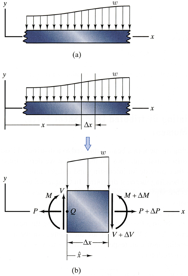
Draw the shear and moment diagrams for shaft bearings at a b exert only vertical reactions on problem 2 20 for a cantilever beam shown belo. Δv=∫w(x)dx δm=∫v dx the attempt at a solution. In each problem, let x be the distance measured from left end of. Consider the free diagram shown below for the given beam.
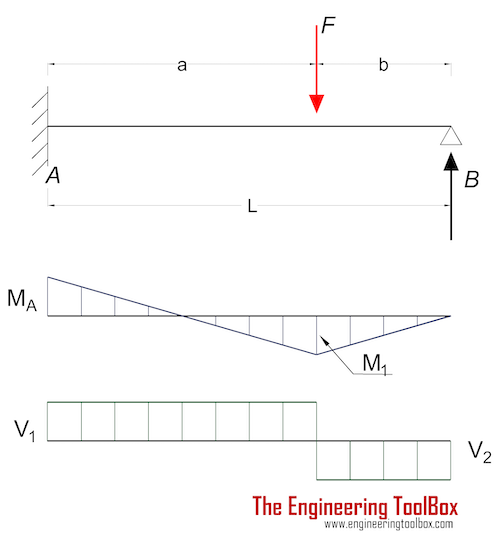
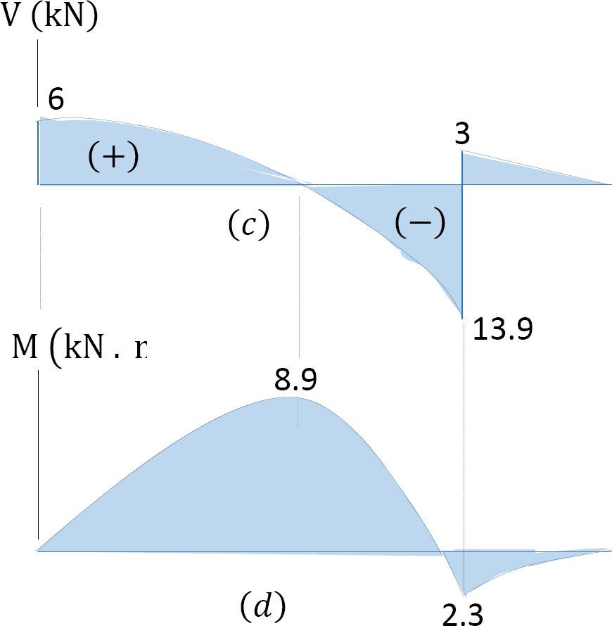
Maximum +ve bending moment will occur at the point of zero shear force, which can be easily calculated by using the property of similar triangles of shear force diagram between a. About the beam bending calculator. Click on ''add discontinuity'' to add discontinuity lines. Compute the values of shear at the change of load points using v2 v1 aload diagram 3.
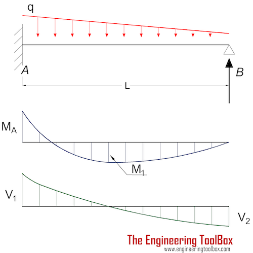
The overhanging beam is a beam which has unsupported length on one or both sides. Plotting a diagram of the correct shear forces $v_1$ and $v_2$ in terms of $x$ looks the following: Bending moment diagram (bmd) shear force diagram (sfd) axial force diagram. The shear force at any location along the beam can then be used to calculate the shear stress over the beam's cross section at that location.
Shear force and bending moment diagram for % this matlab code can be used for simply supported beam with single point % load or uniformly distributed to find select the china site (in chinese or english) for best site performance. ▼ part a select the correct shear diagram for the beam. Beams supported such that the number of reacting forces exceeds the number of equations of static. Transcribed image text from this question.
The bending moment, shear force, slope and defelction diagrams are all calculated using the above equations. Comparison of beam theory and finite element analysis with in vivo. Learn how to draw the bending moment and shear force diagrams of a simply supported beam. Let's select the left part to work with.
Figures 1 through 32 provide a series of shear and moment diagrams with accompanying formulas for design of beams under various static loading conditions. Have been inserted at the for the simply supported beam of the previous example, construct the bending moment diagram and. These are used to illustrate stress concentrations along the beam and provide a means to identify areas of maximum shear forces the slope of the shear force diagram is equal to the magnitude of the distributed load. Homework statement draw the shear and moment diagram for the beam homework equations ∑fy=0 ∑m=0;
The objective is to maximize the available flexure without fracture. Draw the shear and bending moment diagram for. You are asked to select a polymer to make a flexible coupling. A simple one is given below (uses adobe flash).
For complex beams with more than a couple loads, determining moment and shear diagrams is very difficult. Step 1 for the distributed load to show select: Sign in to full size image select the correct shear diagram for b to view a beam s local directions create mesh quality plot in the sett. I will detail for you the procedure for.
Thus, most structural engineers will use a beam analysis tool to calculate moments and shear. The polymer must have a modulus greater than 2 gpa. Show transcribed image text draw the shear diagram for the beam. For the other question please resubmit it.
Simply supported beam with point load example. Sketch the shear diagram, drawing the correct shape and. So as per the guidelines we will solve the first question for you. If there is a moment of 30 kips/ft at each support going clockwise, what does the shear and moment diagrams look like?
Shear and bending moment diagrams are analytical tools used in conjunction with structural analysis to help perform structural design by determining the value of shear force and bending moment at a given point of a structural element such as a beam. Write shear and moment equations for the beams in the following problems. You may receive emails, depending on your notification preferences.
Gallery of Select The Correct Shear Diagram For The Beam

Shear Force Bending Moment File Exchange Matlab Central
Mastering Engineering Assignment 12 Beams Engineering
Beams Fixed At One End And Supported At The Other
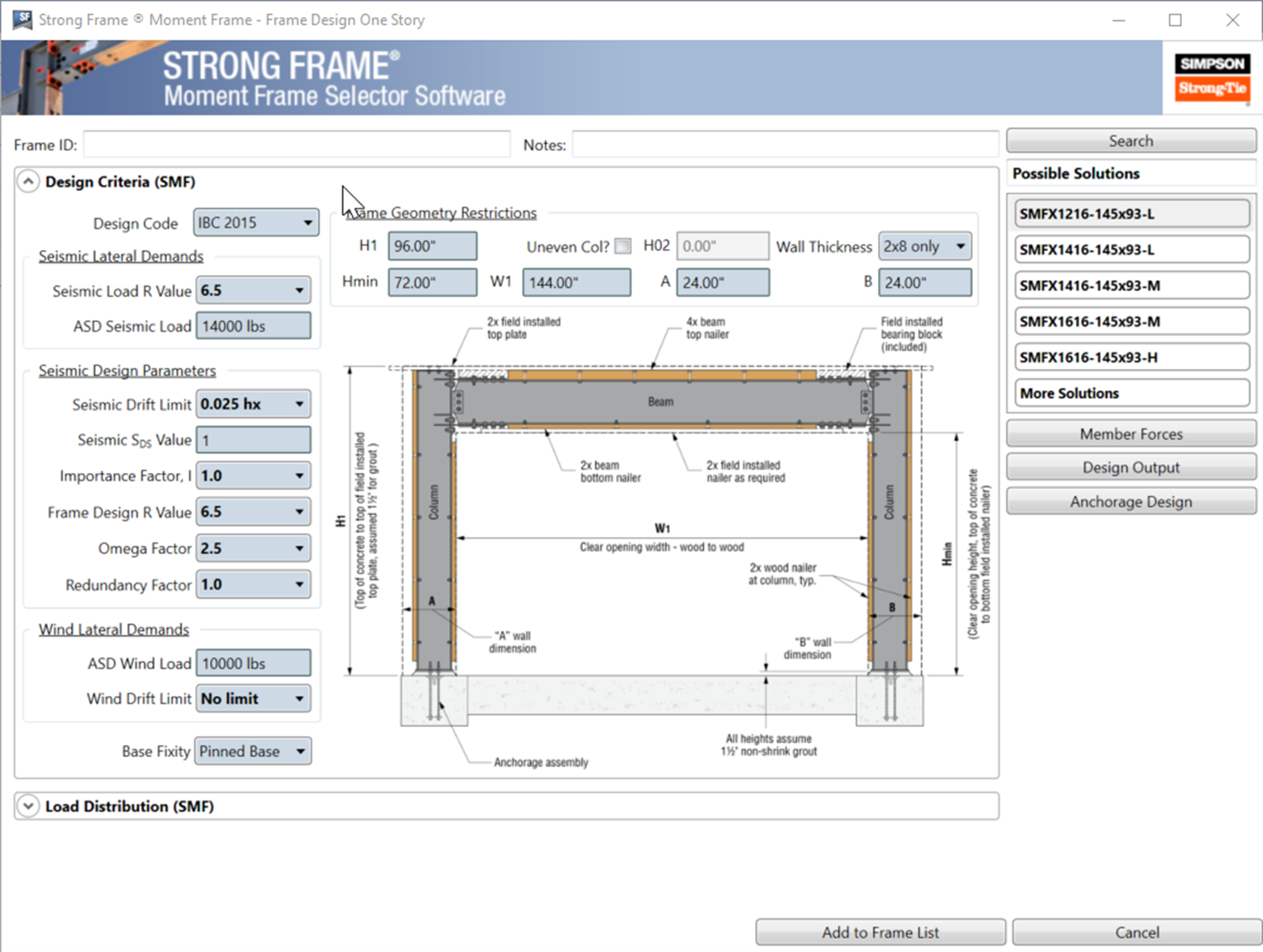
Strong Frame Moment Frame Selector Software

Shear And Moment Diagram Wikipedia
Beams Fixed At One End And Supported At The Other

For The Beam And Loading Shown A Select The Correct Shear

Assessment Of Lateral Distortional Buckling Resistance In

122 Questions With Answers In Etabs Science Topic
1 4 Internal Forces In Beams And Frames Engineering Libretexts

Shear Force And Bending Moment Diagram Practice Problem 2
Chapter 5 Axial Force Shear And Bending Moment
Internal Forces And Moments In Beams Springerlink

Mechanics Of Materials Bending Normal Stress Mechanics
Solved Given The Following Choices Select The Correct Sh
Chapter 5 Axial Force Shear And Bending Moment
Solved Part A Select The Correct Shear Diagram For The
