Orbit Pump Start Relay Wiring Diagram
Upgrading triac soft start with relay.
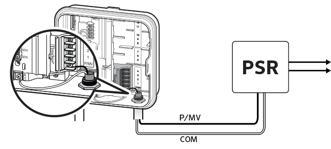
Orbit pump start relay wiring diagram. And as an added convenience, we provide dual common wires (com) to make wiring even more simple. On your web site it shows this diagram with #85 going to ground. 29.05.2018 · intermatic mechanical timer replace support rachio munity from orbit pump start relay wiring diagram , source:community.rachio.com orbit. Quite a few on the market
Want to wire an orbit 57009 to a pump relay. How to wire a submersible pump controller. I don't know if i run + from battery to fuse block then relay or batt + to relay and fuse block to one of. This product allows for an extra zone to be added without having to run wire all the way back to the clock.
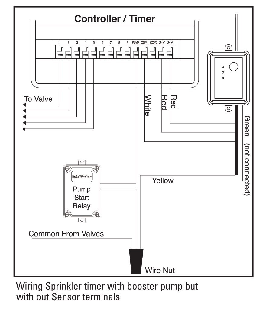
This article will provide an explanation and explore how to wire a water pump for proper operation. Wire com to white wire lead in psr pump, secure with wire nuts. In the wiring in the fuel pump relay #2. Refer to your rain sensor manual for specific wiring instructions.
- John Deere L120 Deck Parts Diagram
- Tecumseh Solid State Ignition Wiring Diagram
- 2005 Ford Taurus Exhaust System Diagram
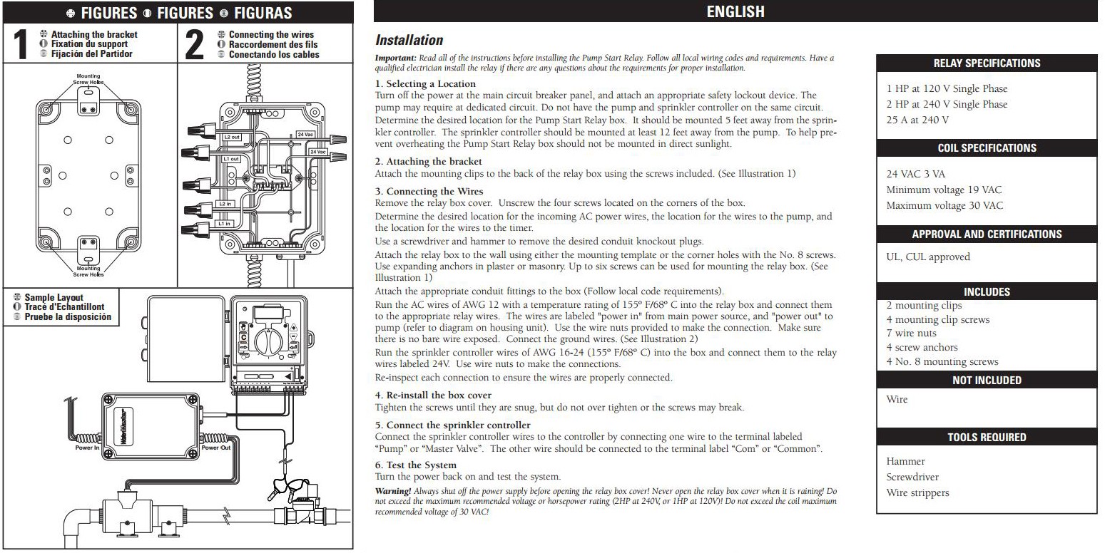
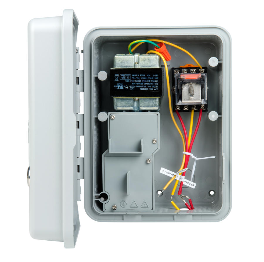
Improper installation could result in shock 2) assemble conduit piping and connect ac power from the power source to one side of the relay (reference wiring diagram and pump start relay. The pump start relay automatically synchronizes your pump for watering with your automatic sprinkler timer. Installation instructions mounting the relay note: Water pumps and advanced wiring.
Are you more of a visual learner? The pump start relay automatically synchronizes your pump for watering with your automatic sprinkler timer. It as the switch seems to be capable of directly controlling fuel pump, but. I am installing the start pump relay orbit to an orbit timer.
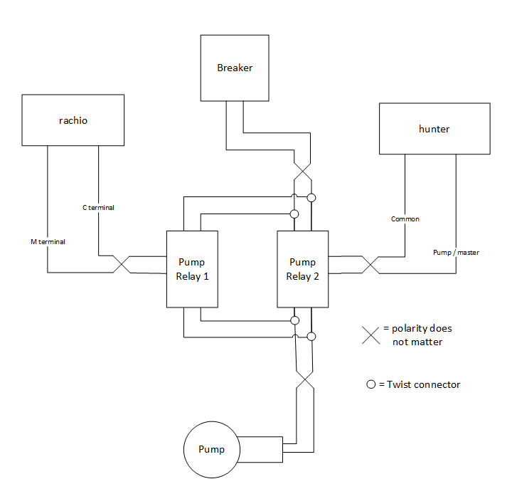
My relay is good but the car still won't start so we took the fuell pump relay out and stuck. This instructable will make you familiar with relay and its working using a simple circuit. Float switch installation wiring and control diagrams. The pump relay has four wires, l1 red in, l1 black out, l2 red in and l2 black out.
Wire power supply • run power supply wires from breaker box (110 v or 220 v). 60 elegant hard start relay wiring diagram. Wire pump • refer to wiring diagram on motor plate for proper voltage and wire. The wires going to it are both red, but pulling them off, i didn't pay attention to whether it made a difference how connected.
Check out our video on water pumps & pump relays! Want to know more about how rachio works with water pumps? A little inspection reveals that the circuit actually does not require the opto coupler circuit at all. A relay is an electrically operated switch.
Psrpt diagram pump start relay/pressure tank combo (submersible well pump) this diagram shows doubler wiring diagram this diagram shows how to wire a product called a doubler. This video shows wiring a franklin submersible pump control box. It is compatible with 24 volt sprinkler systems and has a weather resistant plastic case for outdoor installation. A pump start relay is a relay box that activates a pump every time a zone is activated from the controller.
A fuel pump relay can fail in several ways. Referring to the above diagrams, the first diagram shows a standard light dimmer or a fan dimmer switch circuit using a heavy duty triac bta41a/600. Best savings 2ab85no orbit 57009 sprinkler system 1 or 2 horsepower pump start relay for cheap. How do i install and wire my float switch?
Connecting the pump start relay should only be done by a licensed electrician following local codes. This sprinkler timer allows a master valve or pump. But it works great with my new orbit timmer. 220 volt pump now on 220 volt switch.
I'm wiring up my 12v carter fuel pump and using a relay or is the attached diagram that i made correct. 135 thoughts on start and run capacitor explained. Is there any advantage to installing a 55/5 uf 370. Wiring up an electric fuel pump is pretty simple, and taking a few extra this project will show 2 basic wiring diagrams for electric fuel pumps.
Start relay to operate whenever a station is on. Where can i find a float switch circuit diagram? The 'control' and 'controlled' circuits are electrically isolated from each other. Find solutions to your orbit pump start relay wiring diagram question.
Starter signal from ignition switch or ignition switch relay (lmm) located under hood fuse box. There was no pump start relay separate from the old controller and i do not see that one is installed does anyone know if i need to purchase the orbit pump start relay to complete the operation? Connecting the pump start relay should only be done by a licensed electrician following local codes. Zone valves are the individual valves that operate a group of sprinklers or drip emitters.
Well from the looks of things they don't use a relay with. This video describes how to test a pump start relay for an irrigation system that uses a pump to draw water from a lake or other large water supply. Wire ppe fuel lift pum ground +12v battery constant p #8 7 #8 6 ~ #. 2) assemble conduit piping and connect ac power from the power source to one side of the relay (reference wiring diagram and pump start.
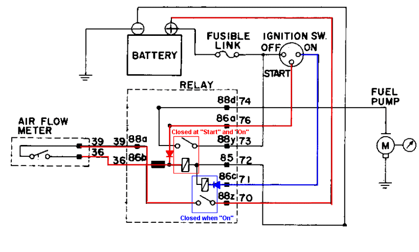
8 5 +12v ignition white wire 3a power diode 10a fuse holder #3 0 10a fuse holder for pump to run when 3 0 10a fuse holder ~. Durable construction provides years of reliable use. If you are activating a pump from this. It states # 86 goes to ground.
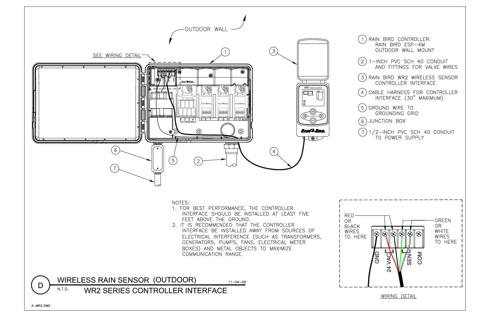
Inner terminals may break, creating an electrical open analyze the diagrams on the relay itself or the wiring diagrams that come in your vehicle repair question: Connect the rain sensor wires to the wiring terminal ports labeled ''sensor''. I have a 40/5 uf 370 volt capacitor currently installed in my heat pump. .pump so i want to no which relay and fuse need to be changed but have no wirring diagram to see whitch one to check and there are so many fueses nad relays dont no were to start can anyone send me a.
Since the generation 2 controller outputs 24vac. I have wiring diagram but can't make out what is says. It is mainly used to control higher voltage circuits with lower voltage.
