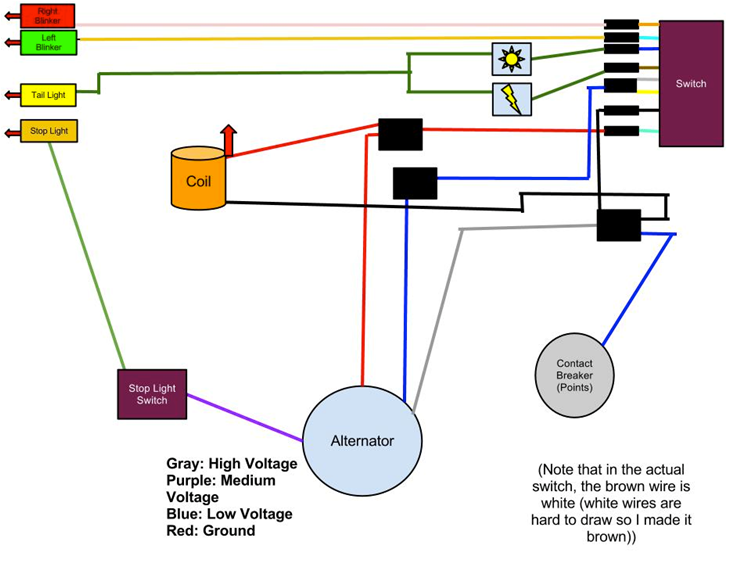
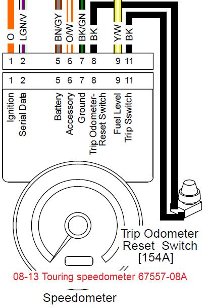
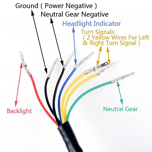
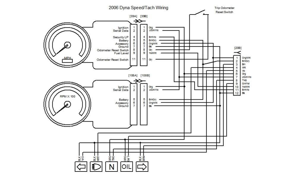
Motorcycle Speedometer Wiring Diagram
I know there's a lot more to this but that's the jist.
Motorcycle speedometer wiring diagram. A 12v motorcycle battery is a 4. Created by aret18 on june 20, 2017, 11:27 a.m. For a free wiring diagram please visit website below: There is a simple version and a version but i'm struggling with how to get my stock speedometer cluster with all its indicator lights connected properly.
Recently, a friend of mine is asking if i can repair his honda wave 125 s speedometer panel that is not functioning. The wiring under speedometer (controlling speedometer, signal lights, head light, gage illumination, re gen and battery charge indicator). Related searches for motorcycle digital speedometer wiring dia motorcycle wiring diagramsmotorcycle wiring diagrams for freeyamaha motorcycle wiring diagramsfree honda motorcycle wiring diagramshonda motorcycle wiring diagrams pdfmotorcycle wiring. Honda has hundreds of small motorcycle models worldwide, with different wirings.
I have uploaded the fz6 wiring diagram. Most italian mopeds, us models. This sounds complicated but its really quite easy. All gauges require 4 things to be connected:
- 2012 Dodge Avenger Fuse Diagram
- 2010 Dodge Charger Trunk Fuse Box Diagram
- 2005 Ford Escape Fuse Diagram
Sometimes, the motorcycle manufacturers help us in this by separating out the wiring for major systems making it easier to decipher them when a problem occurs. Motorcycle lcd digital speedometer odometer. In all the calculation it has been assumed that the speedometer cabel. Device output to which the speedometer is connected the value of the output frequency scaling.
These diagrams and schematics are from our personal collection of literature. The range can be increased up to 999 kmph by adding another the same speedometer can be used other vehicles by making similar calcualtions. Start with the ignition switch in the middle of the page. Other color available for 2013.
Minarelli wiring diagram for testi/gitane & others. In most modern motorbikes the information sent to the speedometer is embedded within a protocol, so it is hard to «read» that info from there. Typically, this feed wire is red. The electronic speedometer in this instrument is designed to operate with 1.
That's where the motorcycle wiring harness comes in. Some motorcycles have electronic speedometers that require calibration and repair. If you have any questions, please feel free to email. Harley davidson wiring diagrams and schematics good luck.
They consist of a speedometer gauge and a speedometer cable that connects between the gauge and a fitting on the front wheel hub. The cable spins a magnet around at the same speed inside the speed cup. Close perusal of my fsm (the section of the wiring diagram labled combination meter) along with the speed sensor wiring yielded the following info Wiring diagram ( pin out ) speedometer vario 125/150.
Does someone knows were or have them? I've wired a few of these speedometers in the past and for the price of them i am surprised to say. I will try posting the wiring diagrams, but if i can't figure that out they are online too. Wiring diagram of external map sensor.
The key switch is fed from the main circuit breaker, later, the maxifuse. As you can see, number 34 is the speedometer, and the speed and rpm wires are not connected to the speedometer. If speedo still does not work check wiring connector pins from sensor to speedometer. Whether you need an electronic speedometer for a car, truck, motorcycle, boat, van, utv, atv or a tank, the installation is the same.
Robertgilkin@gmail.com we have a motorino xma 2017. This speedometer can measure up to 99 kmph with a resolution of 1 kmph. A 12 v power source must be used to power this speedometer. Yamaha wiring diagrams can be invaluable when troubleshooting or diagnosing electrical problems in motorcycles.
While these wiring diagrams may seem confusing there is a method to their madness. Gerneral wring for mqcon controller and ca. Motorcycle manuals pdf, wiring diagrams, dtc. Electrical and technical automotif blog.
Color motorcycle wiring diagrams for classic bikes, cruisers,japanese, europian and domestic.electrical ternminals, connectors and supplies. The speedometer cable, powered by the driveshaft, turns as well. When the engine turns over, the driveshaft turns to make the wheels spin round. Easy how to video on wiring one of these speedometers.
Hello guys im trying to make a swap but i cont find anyware a full wiring diagram from the 8th gen civic speedometer and tachometer. Contribute to brickpool/speedometer development by creating an account on github. Parameter use built in map built in map the speedometer can be connected to one of the outputs for stepper motor or free injector / aux. Power, ground, lights and signal.
There are many different ways to wire your bike, but for this tutorial we're going to assume that your factory harness however, if your plug wires are damaged or you suspect a failure, it's always a good idea to replace them with something new. Typical motorcycle speedometers are not complex pieces of equipment. My choppers original speedometer 2:1 ratio.


