Start Stop Push Button Wiring Diagram Single Phase

Practical Machinist Largest Manufacturing Technology Forum
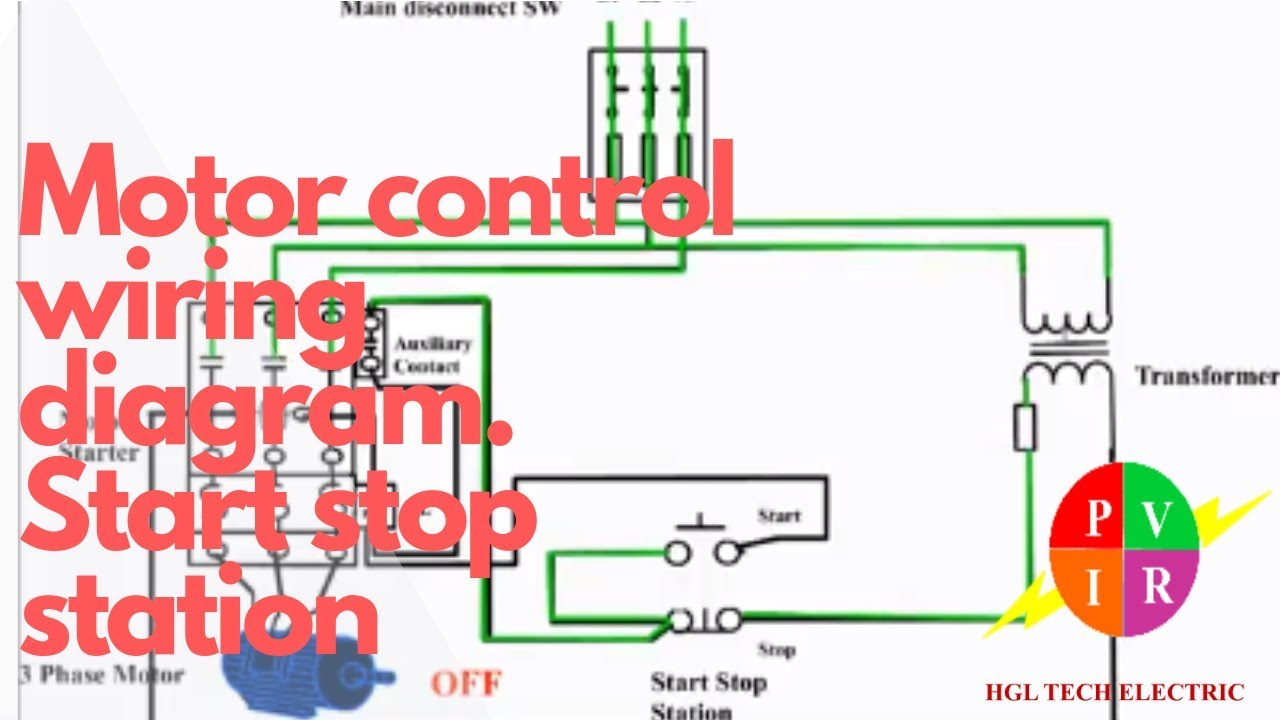
Motor Control Start Stop Station Motor Control Wiring Diagram How To Wire Start Stop Station
Forward Re Verse Control Developing A Wiring Diagram And
When we press push button, relay should be on, it means we use normally open type push button because when we press this switch supply goes forward.
Start stop push button wiring diagram single phase. Pband sresd inputs withstand voltage up to ±15. The wiring diagram for a dol stater is shown below. Then wire one of the contacts in use the top diagram to help you figure out how to wire it. Single push button on off wiring diagram.
Push button circuit wiring diagram 0 0 4 reference point identified on starter corresponds with number shown in push wiring diagram for push button start new start stop push button. Hey all, long time reader, first time poster. Littelfuse push pull switches are designed for universal applications within harsh environments. And provide a acknowledge/reset button to stop the hooter.
Push button circuit wiring diagram /0 junction of , product data typical wiring diagrams for phase motor 3 wiring control diagram with run and jog 3 phase ac motor start by scr circuit text circuit wiring diagram single phase reverse motor text: Recommended for the safety of people and objects. And on next switch press, it starts the movement from the current position. Stop/reset this button places the module into its stop/reset mode.
You can make that process easy by grabbing a library like bounce2. If you are having problems writing a sketch directly then it may be worthwhile to draw a petri net diagram of your system and add the logic of your. This application contains the start stop wiring diagram push button. Power & control wiring trending.
This application contains the start stop wiring diagram push button. The application is loaded to make it easier for you to learn about electricity that helps you in knowing the electrical circuit. In this servo control push button project, the clockwise and anticlockwise movement of the servo shaft is controlled by two push buttons.how to use a servo whenever the push button has released, the arm movement stops. Thank you, may be useful.
An additional normally open acknowledge overload reset push button, which is connected to the input module, allows the operator to reset the. Главная страница » приложения » работа » start stop push button wiring diagram. Also in same time, relay has to activate a hooter which is powered by 230v ac. This is for a friend of mine who has a wood jointer across the street.
What is the wiring diagram and what is it good for? Because a button becoming pressed isn't the same as a button that is pressed. On delay function closing the external reset switch immediately resets the timer. The application is loaded to make it easier for you to learn about electricity that helps you in knowing the electrical circuit, many diagrams about start stop wiring push button diagrams that you can learn in full, the categories.
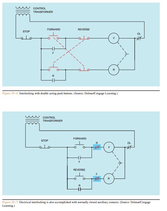
Engine start stop push button switches datasheet. Push button switch (pushbutton switch) is a device / simple switch that serves to connect or disconnect the flow of electricity with the working system press unlock (does not lock). Wire your trainer so that pressing push button 1 energizes the contactor and it stays latched in until you press push button 2. The stop push button has address 000, while the normally open sides of the forward and reverse push buttons have addresses 001 and 002, respectively.
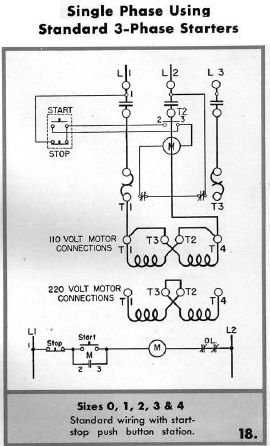
Wiring diagram a wiring diagram shows, as closely as possible, the actual location of all component parts of the device. A single phase induction motor can not do work as a 3 phase can done. This will clear any alarm press the stop button at any time to exit the event log viewer. The start button is normally open and the stop button is normally closed.
1 phase & 3 phase wiring. Single push button start stop connection. Indication of shutdown alarm logged (eg return feed for senders*. For 3 phase motor we use some for 3 phase induction motor start/stop we use always mc contact or.
This application contains the start stop wiring diagram push button. This is how to run wiring for a toggle onoff switch and a push button start. It's is a type of electric relay which for motor contactor wiring we use push button switches for switching on/off the motor. Learn vocabulary, terms and more with flashcards, games and other study tools.
We hope this application helps you learn the start stop push button wiring diagram.
Gallery of Start Stop Push Button Wiring Diagram Single Phase

Bvpow Motor Start Stop Push Button Motor On Off Switch With Surface Waterproof Dustproof Box Mount Kao 5h 10a Ac 220 380v
Start Stop Jog Circuit Motor Control Circuit Diagram

Diagram Eaton Magnetic Starter Wiring Diagram Full Version

Multiple Push Button Stations
How To Wire A Start Stop Station Controlling A 120 Volt

Multiple Push Button Stations
Diagram Wiring Diagram Motor 3 Phase Full Version Hd Quality

How To Build An Auto Start Rotary Three Phase Converter

Motor Starters Product Guides
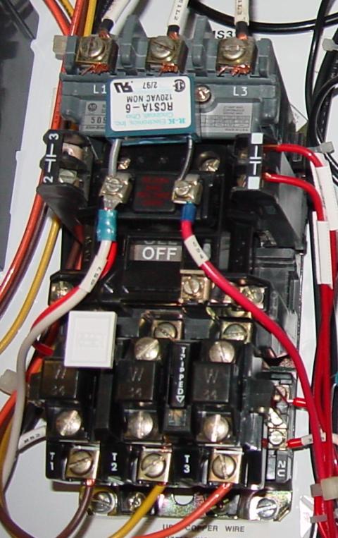
Magnetic Starter Wiring An Allen Bradley 709 3 Phase Starter

F9308e 3 Phase Motor Starter Relay Wiring Diagram Wiring

Ok 2229 Emergency Stop Wiring Diagrams Schematic Wiring

On Off Three Phase Motor Connection Power Amp Control

Three Wire Control Circuit

Diagram With Start Stop Switch Motor Wiring Diagram Full
Motor Circuits And Control Applied Industrial Electricity

Practical Machinist Largest Manufacturing Technology Forum
