Lng Process Flow Diagram

Lng Fundamentals Sciencedirect

Solved The Process Of Lng Liquefied Natural Gas Regasif
Optimized Process Schemes For Lng Lbg Production Gasp
It's quick, easy, and completely free.
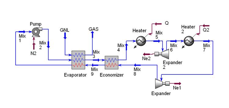
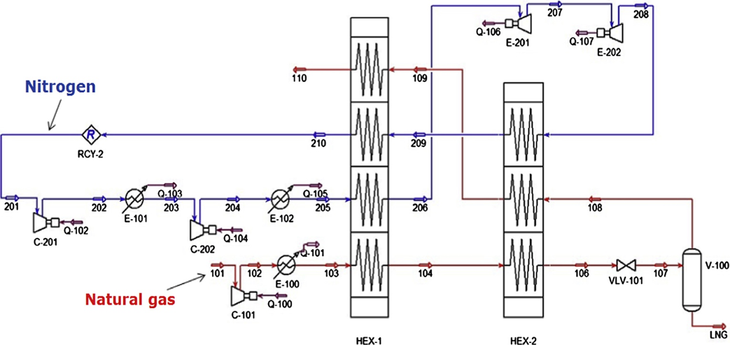
Lng process flow diagram. The process flow diagram (pfd) represents a quantum step up from the bfd in terms of the amount of information that it contains. Overview lng terminal flow diagram process description recondenser design detailed description of the figure control systems to bog recondensation process. By optimizing eleven variables including the outlet pressures of all compressors and throttling valves and the molar flow rate of the mr components. Stream flow rates and compositions;
From planning to information management, from capacity management to resource organization, and from decision analysis to cost calculation, etc. Greenhouse gases, natural gas and gasoline | researchgate, the professional network for scientists. Visual paradigm online includes a rich set of symbols that covers all the elements you need for chemical. Expressed using the bpmn standard, they describe the sequence of tasks.
Process selection and recent design innovations for lng different types of natural gas liquefaction plants have been developed across the world to meet rising demand for lng. This information paper describes the process used there are different designs of lng import terminals but the overall process is often quite similar. They're the ones that indicate the. Process flow diagram (pfd) captures process flow for a plant.
- Farmall Super M Wiring Diagram
- 02 Dodge Ram 1500 Radio Wiring Diagram
- John Deere Model B Engine Diagram
Process flow diagrams show sequential flows of control between activities and may utilize swim lane techniques to represent ownership and realization of process flow diagrams describe the internal functioning of processes. This investigation focuses on the lng generation process during the transients in ng flow. Get to know bpmn process flow diagram symbols and how to use them in your process diagrams to optimize your organization's workflows. Summary of liquefaction technologies the foregoing processes are summarizes in table 6 with respect to:
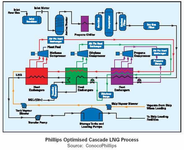
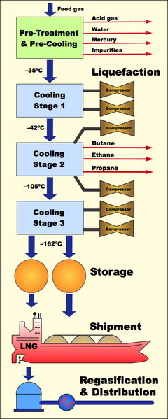
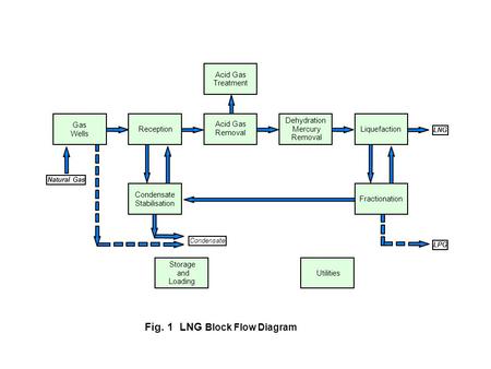
They define when a process starts, when it finishes, what tasks occur and what deviations happen inside the flow and tasks. 1 lng block flow diagram acid gas treatment dehydration mercury removal gas wells acid gas removal reception liquefaction lng natural gas condensate stabilisation fractionation linde mixed fluid cascade process (mfcp) process gas precooling liquefaction subcooling lng fig. Lng must be turned back into a gas for commercial use and this is done at regasification plants. This analysis assumes that the only processes the regasification plant will perform are pumping, compression and vaporizing lng (fig.
Unece wpg lng chapter 2. Below is a basic diagram, which can be used for simple processes that don't possess complicated procedures. A process flow diagram provides a method of defining the steps in a process. The process flow diagram above helps an individual understand how a project team is empowered.
21 process flow diagram 3: Process flow diagrams in just about any industry to organize process steps in sequential order. A flow process chart is a chart showing the sequence of the flow of a product by way of recording all activities/events under review with appropriate symbols. A process flow diagram (pfd) is a diagram commonly used in chemical and process engineering to indicate the general flow of plant processes and equipment.
Due to the inflow of heat transfer from the surroundings to cryogenic lng, it is unavoidably vaporized generating bog (boil off gas) in. A pfd does not show minor components. Process flow diagrams are required for the following reasons: Pfds are used for visitor information and new employee training.
Pfd also tabulate process design values for components in different operating modes, typical minimum, normal and maximum. Process flow diagram (pfd) is a drawing which essentially captures the process flow for a processing plant. This is why process flow diagrams are useful as training tools. A process flow diagram (pfd) is a diagram used in chemical and process engineering to indicate the general flow of plant processes and equipment.
Process flow diagrams (pfds) are used in chemical and process engineering. Lentransgaz [34] developed new natural gas liquefaction equipment that uses the pressure energy to liquefy the natural gas without an external energy source. The pfd contains the bulk of the chemical engineering data necessary for the design of a chemical process. This chart is similar to operation process chart with the difference that it utilizes symbols of operation, transportation, inspection, delay and.
Plant design basis a clear understanding of the working of the equipment. It captures main equipments, process streams, design conditions and process if the flow of gas to vent/flare stack stops for some reason, there is a possibility of air ingress into the flare stack and into the vent ko drum, vent. Process flow diagram (pfd) illustrates the arrangement of the equipment and accessories required to carry out the specific process; The process flow diagram (pfd) is a critical component of process design.
Want to make a process flow diagram of your own? Learn how to create a process flow diagram with keji giwa learn more at: Jian gong and fengqi you. 01.09.2015 · process flow diagram of apci lng liquefaction process.
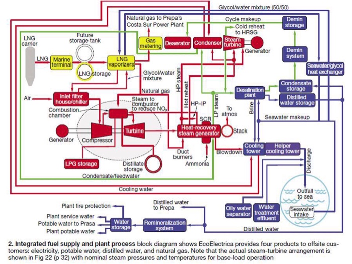
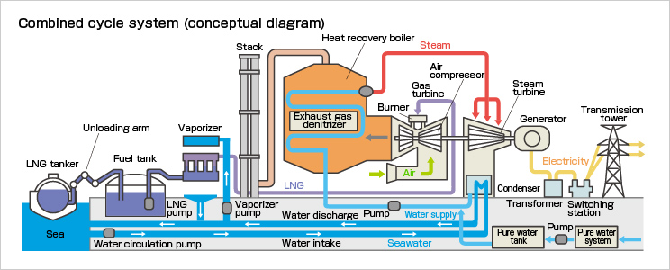
A typical lng import terminal process flow diagram is. These diagrams show the flow of chemicals and the equipment generally, a process flow diagram shows only the major equipment and doesn't show details. This is essentially the basics of what a process flow diagram is and how they are used in the process and other industries depict a process. High efficiency cooling is necessary to liquefy the natural gas by condensation.
The pfd is a diagrammatic representation of the process. For all of the diagrams discussed in this chapter, there are no. 6 distillations are used in process flow diagram 1 and 5 reactors. Generally, a process flow diagram is an indispensable tool in modern engineering application since it can be used in various stages of process engineering:
A variation of the process flow diagram is a utility flow diagram (ufd) which captures the essence of utilities required for the process such as, steam, nitrogen, water etc.
Gallery of Lng Process Flow Diagram

Malaysia Lng Terminal Google Search

Typical Process Diagram Of Small Lng Refasification
Solved A Name Of The Power Plant B Flow Diagram Of The

Liquefied Natural Gas Process An Overview Sciencedirect
Solved 1 Make A Process Flow Diagram From The Image 2
Chpt 4 Natural Gas And Lng Tech

Diagram Process Flow Diagram Lng Plant Full Version Hd

Liquefied Natural Gas Process An Overview Sciencedirect

The Apci C3 Mr Process Part 2

Diagram Process Flow Diagram Lng Full Version Hd Quality
Liquefied Natural Gas Technology Choices And Emissions

Simplified Lng Process Flow Download Scientific Diagram

Oerc Lng Production Process

Wrg 8579 Process Flow Diagram Lng Plant

Diagram Process Flow Diagram Lng Plant Full Version Hd
Simultaneous Production Of Lng And Ngl Ppt Video Online
Natural Gas Liquefaction Processes Design And Optimisation
