Lng Plant Process Flow Diagram

Diagram Ethanol Plant Flow Diagram Full Version Hd Quality

Steppin Out With My Lng The Liquefaction Train Ramp Up

Midstream Facilities Abb
Abstract simulation and integration of liquefied natural gas (lng) processes.
Lng plant process flow diagram. Download lng plant process useful. Pfd also tabulate process design values for components in different operating modes, typical minimum, normal and maximum. Heavier hydrocarbons are then removed using high level refrigerant to prevent freezing and. The pfd contains the bulk of the chemical engineering data necessary for the design of a chemical process.
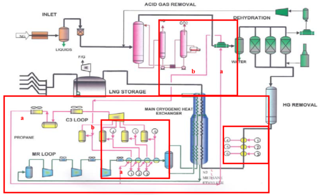
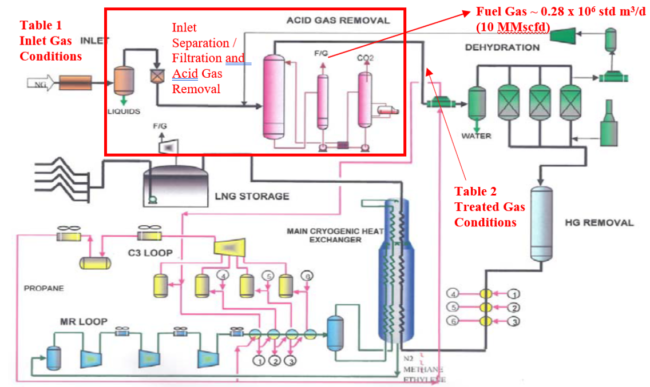
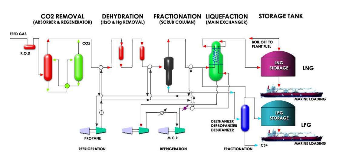
1 lng block flow diagram acid gas treatment dehydration mercury removal gas wells acid gas removal reception liquefaction lng natural gas condensate stabilisation fractionation linde mixed fluid cascade process (mfcp) process gas precooling liquefaction subcooling lng fig. Natural gas finishes third (quadrillion btu) among fuels used for energy generation after petroleum and coal, but the gap between coal and natural gas is narrowing and has occasionally closed in recent months [1]. • all sections of the feed gas pipeline including the mainland section, the tunnelled section under port. At the receiving end, facilities are required to store the received lng and reconvert it back to gas for use by consumers.
Summary of liquefaction technologies the foregoing processes are summarizes in table 6 with respect to: Process flow diagram (pfd) captures process flow for a plant. As concern over global warming and environmental problems grows worldwide, there is increasing demand for natural gas as an at an lng plant, the liquid components (condensate) are removed from the natural gas that was produced from the gas field. Process flow diagram (pfd) which is also known as process flow chart, process flowsheets, and process flow scheme.
- 97 Chevy 1500 Brake Light Wiring Diagram
- 2007 Nissan Altima Fuse Diagram
- 2005 Dodge Ram 1500 Fuel Tank Diagram
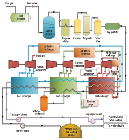
The process flow diagram (pfd) represents a quantum step up from the bfd in terms of the amount of information that it contains. A simplified process flow diagram of the conocophillips optimized cascade® process is shown in figure 1. A process flow diagram is key to the development and management of an industrial production process. Prior to the liquefaction process, the feed gas, which flows directly from unece wpg lng chapter 2.
Natural gas liquefaction is a process which typically involves several steps: For all of the diagrams discussed in this chapter, there are no. Lng processes phillips optimised cascade and air products (apci) processes dominate the lng plants currently under design, construction & operation new processes include: Lng must be turned back into a gas for commercial use and this is done at regasification plants.
It captures main equipments, process streams, design a variation of the process flow diagram is a utility flow diagram (ufd) which captures the essence of utilities required for the process such as, steam, nitrogen, water etc. The flow lines then run to the gas plant inlet metering and manifold skid where each well's production is the gas from hp production header flows into a three phase inlet separator for separation. This chapter describes the liquefied natural gas (lng) plant components and ancillary facilities and their construction, operation and decommissioning, with the exception of the following components: The conversion of natural gas to its liquefied form allows for the transport of greater quantities.
Read this guide to know every blocks in bfds can represent anything from a single device to the entire plant, and links between blocks represent process flows (liquids, solids, gases etc.). Raw natural gas is composed of several gases. Natural gas liquids (lease condensate, natural gasoline, ngl) are components of natural gas that are liquid at surface in gas or oil field facilities or in gas processing plants. Process flow diagram (pfd) is a drawing which essentially captures the process flow for a processing plant.
The global demand of liquefied natural gas (lng) has risen rapidly in recent years for the reasons of energy security and sustainable development. The lng process mainly addresses transportation needs for lng. Liquefied natural gas (lng) to storage. In this article, you will learn.
A process flow diagram (pfd) is a diagram commonly used in chemical and process engineering to indicate the general flow of plant processes and notation library for process flow diagram. This has led to considerable recent research interests and efforts in the lng production chain and associated risks in handling, storage. This information paper describes the process used to produce and ultimately deliver lng to consumers. Download lng plant process flow diagram for free.
And what type of information provided in it with the help of real plant process flow diagram example. In this liquefaction process, multiple several lng projects are feed gas flow constrained. Liquefied natural gas (lng) plants. Gas processing provides news, business information and projects information for global gas the overall production availability of an lng plant is a major criterion for economic evaluation.
The process block flow diagram of a nonintegrated ngl recovery plant and an lng liquefaction plant is shown in fig. A process flow diagram (pfd) is a diagram used in chemical and process engineering to indicate the general flow of plant processes and equipment. Processes • equipment for liquefaction • novel plant concepts • concluding remarks. A process flow diagram (pfd) is a diagram commonly used in chemical and process engineering to indicate the general flow of plant processes and equipment.
A pfd does not show minor components. All formats available for pc, mac, ebook readers and other mobile devices. Visual paradigm online includes a rich set of symbols that covers all the elements you need for. Natural gas processing with flow chart.
The production loss due to lng storage and loading facilities is addressed on a. Pfd is used to capture the main process equipment's, main process stream, process/design conditions in these equipments and the basic process control scheme in a single.
Gallery of Lng Plant Process Flow Diagram

Lng Liquefaction And Purification Processes Aong Website

Diagram Process Flow Diagram Gas Plant Full Version Hd

Process Flow Diagram Pid Nitrogen Generation Membrane Package

Lng Fundamentals Sciencedirect
Solved A Name Of The Power Plant B Flow Diagram Of The
Liquefaction Technology Selection For Baseload Lng Plants
Process Selection And Recent Design Innovations For Lng

Diagram Process Flow Diagram Lng Plant Full Version Hd

Lng Fundamentals Sciencedirect

Natural Gas Liquefaction Processes Design And Optimisation
Campbell Tip Of The Month
Campbell Tip Of The Month

Figure 3 From Liquefied Natural Gas Lng Vapor Dispersion
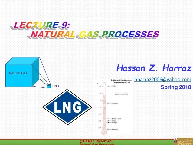
Lecture 9 Natural Gas Processes

Liquefied Natural Gas Process An Overview Sciencedirect

Process Control And Automation Of Lng Plants And Import
Interview Kerja Liquid Natural Gas Process In Pt Badak Ngl
