Honda 3 Wire Speed Sensor Diagram
Transzex:i'm having fun on my budget.
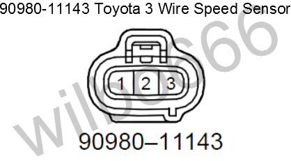
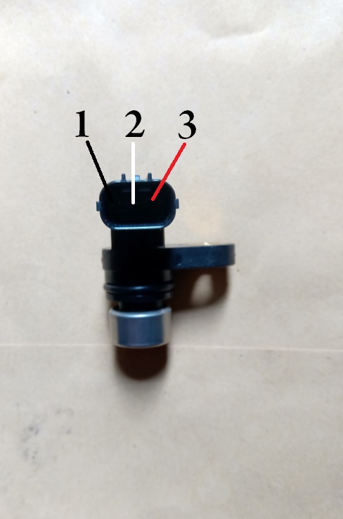
Honda 3 wire speed sensor diagram. Speed sensor location included here. Remove a jumper wire from the abs modulator. Since the 3 wire sensors are use our dual fan wiring diagram and guide to make sure you properly wire your fans to your thermostat. Unplug the sensor wire harness from the vss step 2.
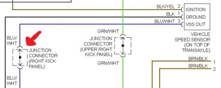
Short the red/black and green/orange #1 wire. 480 x 360 jpeg 11 кб. On my truck, one is black/orange and comes from the gauge fuse, so i'm presuming that it is close perusal of my fsm (the section of the wiring diagram labled combination meter) along with the speed sensor wiring yielded the following info The speed sensor indeed has three wires going to it.
The wheel speed sensor is the essential component that the pcm uses to calculate vehicle speed. This thing is very accurate once callibarated. It can be installed on any other. It's always good to do this when working with electronics.
- Lawn Mower Charging System Diagram
- 2003 Toyota Corolla Fuse Diagram
- 2004 Gmc Envoy Xl Radio Wiring Diagram
.sensor signal (if connected), and the engine rotation speed (calculated from the measured time first of all, let's have a look at the wiring diagram. 2011 honda odyssey output speed sensor blue plug green gray red wires need diagram. 2,083 3 wire speed sensor products are offered for sale by suppliers on alibaba.com, of which sensors accounts for 7%, auto sensors accounts for 1%, and bicycle computer accounts for 1%. Does anyone have the wiring diagram for a 2003 np231j transfer case speed sensor?
Guide a 12 mm socket with two 10 extensions down onto the bolt. Fuelino is connected as a man in the middle however, fuelino application is not only limited to honda cbr125; Logic ground line open circuit inspection. 1 x speed sensor connector.
Try autozone.com to see if they have your car listed for diagrams pictures and step by step instructions if your car is not listed then try your local library they have all the car manuals and even copy them for. Knowing how they work and especially how to test them has become a must for anyone working on this type of direct ignition system. You will need to carefully work the socket and extensions between wires and hoses, being careful not to put too much tension on them. The speed sensor and reverse gear sensor is for dead reconing.
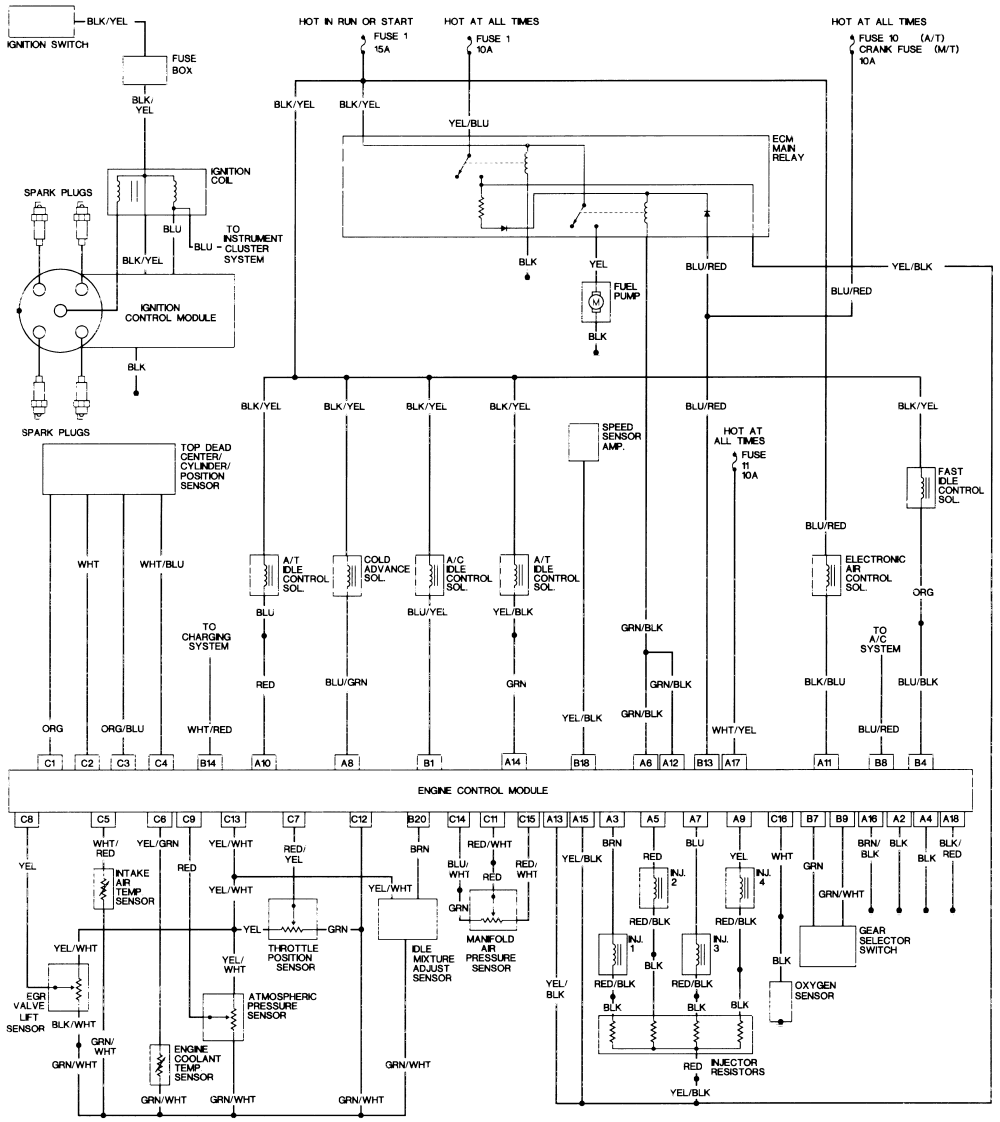
Ground provided by the middle wire of the map sensor connector. I just want to ask if anyone have a detailed diagram of the engine harness for 93. The speed control pwm injection is implemented through 3 separate half bridge npn/pnp drivers stages, controlled with a spwm feed from an ic 555 pwm generator as seen in our previous designs. Honda accord cars are available in two body versions:
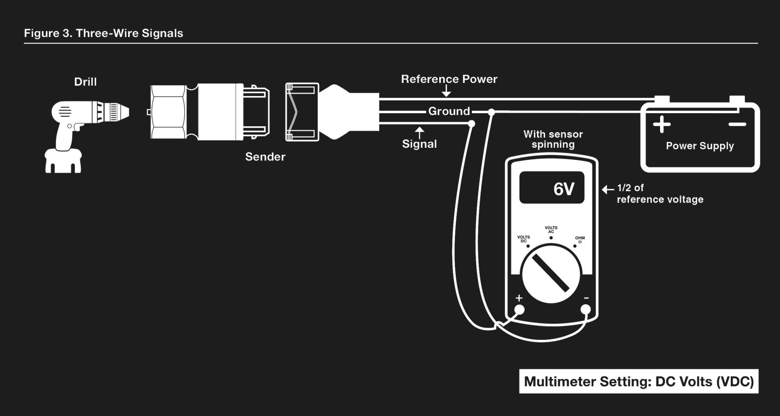
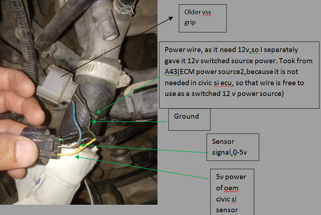
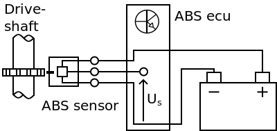
I'm going to assume perhaps that the differences in plugs are between an lx and ex/exl, although im not certain. Can somebody tell me the order of which the pins need to be in, that would be greatly appeciated! The 3 wire speed sensor output signal is a square wave signal that connects between the input power source (battery voltage) and the power ground. A wide variety of 3 wire speed sensor options are available to you, such as position sensor, magnetic.
My new beater pm me for wire diagrams and other honda computer stuffz. Your honda civic's fuel system is a speed density type. Note that the external wiring diagram in this sensors and wiring section is entirely separate from, though. Air gap inspection support the motorcycle securely using a hoist or 7.
Digital wave is produced as tone wheel rotate according as hall sensor principle. Right now my speedometer isn't working and i hope that it's the wiring for the speed sensor. The 3 wire speed sensor is externally powered, so you will need a power source of some form. In basic diagram, there are four wires that connect to the motor:
In terms of which speed sensor wires do i tap into i believe the blitz requires two speed inputs and i dont have a wiring diagram for it.(used buyee to buy. Wiring diagrams and free manual ebooks: I have an orange, purple and white with orange stripe coming off the sensor. Vehicle speed sensor female (92up), 3 wire ckf female (96up), egr (92up).
I purchased ah honda vezel but i need ah detail wire diagram showing the colours so i can retain my oem camera system. 763 x 637 jpeg 58 кб. I bought this one off of ebay element owners club is your go to forum community to discuss your honda element, and get ideas from your next great trip to your next honda element mod. Some honda accord wiring diagrams are above the page.
(this wiring diagram is for those creating their own harness for a v2.2 all megasquirt® installations must have an input (tach) signal to determine engine speed. The three pins connected to the connectors came out. Testing a 3 wire (hall effect) speed sensor is nearly as simple. Note which wires old fan switch connects to before starting.


