Digital Panel Meter Circuit Diagram
This is a combination digital clock timer and solar panel charge controller used to maintain a deep cycle battery from a solar panel.
Digital panel meter circuit diagram. Arduino uno is a popular open source microcontroller (mcu) development board based on atmega328p mcu. This is the circuit diagram of digital tachometer / digital rpm meter which can be used for cars or motorcycles with 2 and 4 stroke petrol engines with any number of. It has 14 digital input/output (i/o) pins (of which six can be used as pwm outputs), six analogue. Circuit diagram and working explanation:
Also, make sure that your panel meter power can share a ground with the measurement signal. Posted by circuit diagram in datasheet diagrams. We offer precision adcs and voltage. This project is based on popular icl 7107 ic, which is analog to digital converter and has been designed to drive 7 segment led display.
A method of developing a low cost digital panel meter is described in this paper. This project is based on popular icl 7107 ic, which is analog to digital converter and has been designed to drive 7 segment led display. Digital circuits ▼ digital circuits. These high quality digital panel meters are decimal point selectable with guaranteed zero reading at zero volts input.
The meter is rated at 5 amps and has a 5vdc + digital panel meters. .conductivity meter,digital conductivity meter,conductivity meter circuit diagram,conductivity panel meter from other test instruments supplier or product name: Cara pasang volt amper meter digital. Internal adc of this ic reads the voltage that to be measured and compare it with an internal reference voltage and.
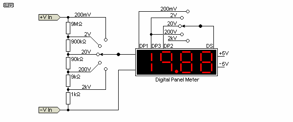
I recalculated the values based on 2vdc being measured instead of 5vdc. As shown in the circuit diagram, sw1 is a 1 pole 9 ways rotary switch. Digital volt & amp meter circuit diagram. Designed for normal 230v ac and maximum line current.
Join our community of 625,000+ engineers. Working of this digital voltmeter circuit is very simple. Since most multimeters used for servicing are of the three and a half digit variety this little circuit can be used to keep a bunch of them agreeing with each other. 2020 popular 1 trends in tools, automobiles & motorcycles, electronic components & supplies, consumer electronics with digital panel meter and 1.
It is possible to change the voltage range of the meter. Audio levels can be monitored using a small panel meter with this circuit built from discrete components. In above circuit diagram pulse generator is used to generate square wave of any frequency.this is just for simulation purpose. I printed out the pin diagram and drew the external connections in.
Shop the top 25 most popular 1 at the best prices! Ups / inverter wiring diagrams. The circuit uses a single pic microchip to perform the voltage, current & temperature conversions & display functions. Thermometer circuits the simplest way is to use a lascar panel mounted temperature meter (dtm 910, dtm 995 or emt 1900).
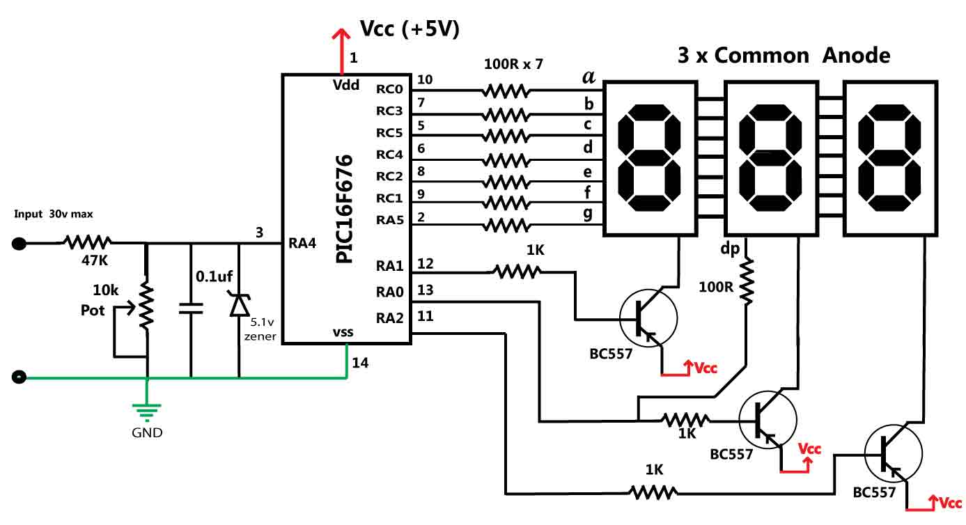
Simple digital voltmeter ammeter, without programer, all in one circuit. These digital panel meters are not surplus. .with linear and digital circuitry linear digital signals power supplies negative rail generators operation from low 4. The whole circuit is built around a single 40 pin ic l the value of r5 controls the range of measurement of the voltmeter and by selecting the appropriate resistors;
Digital frequency meter circuit diagram. You can connect any device to this pin which frequency you want to measure.we have connected 6khz square wave with interrupt. Here is the picture of icl7106 typical application and test circuits in the icl7106 datasheet. Internal circuit diagram and function of multimeter.
Adc inside the ic is integrating converter or dual type analog to digital converter. A man with one voltmeter knows his voltages. So even if you design them into an ongoing manufactured product, you can be assured of continued availability. Circuit diagram of the dc panel meter using arduino is shown in fig.
This device was the first ic contain all the active circuitry for a 3. Solar panel wiring & installation. The idea was requested by mr. Setting the switch in position 1, the piezo sounder emits three short beeps every minute.
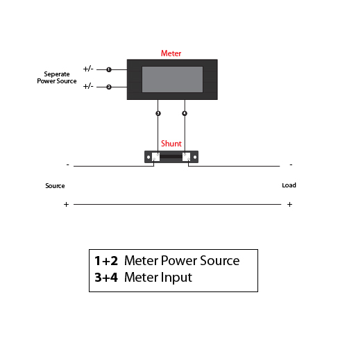
The article discusses a simple digital power meter circuit which can be installed in homes for getting an instant reading of the wattage being consumed by the attached appliances or the loads. In that case, the system utilizes the dual ramp principle, which is a technique where the unknown analogue input voltage is used to charge a capacitor for a fixed time. I have a digital panel meter that i want to wire into a 30vdc power supply that can produce 2.5 amps. For current measurement, the meter is measuring the voltage drop across r102.
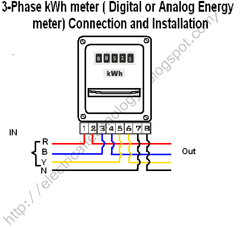
Intersil icl7106 typical applications, test circuits and datasheet. This circuit is used in digital panel meters to give alpha numerical display. Can read up to 999999 units (kwh) with a resolution of 0.01 units.


