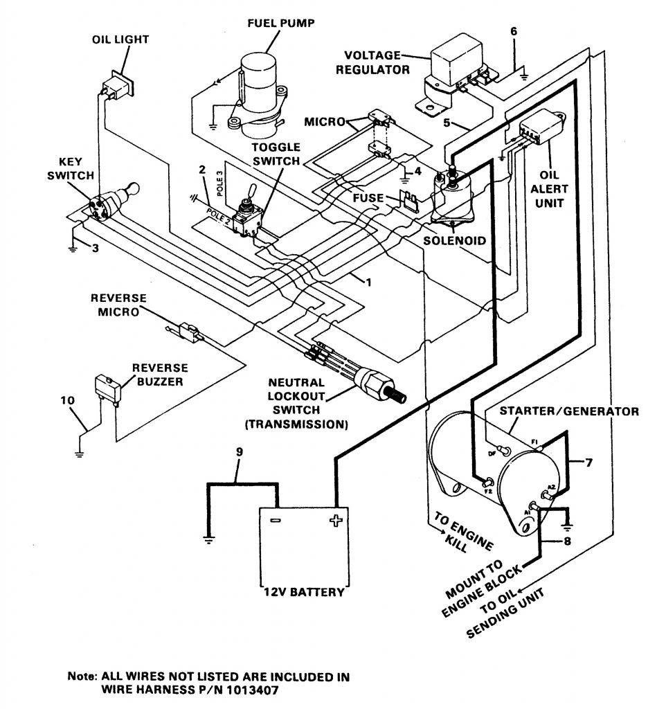
Ansul System Wiring Schematic
(this wiring diagram is for those creating their own harness for a there are two wires on the external wiring schematic that go from megasquirt® into the tps sensor.
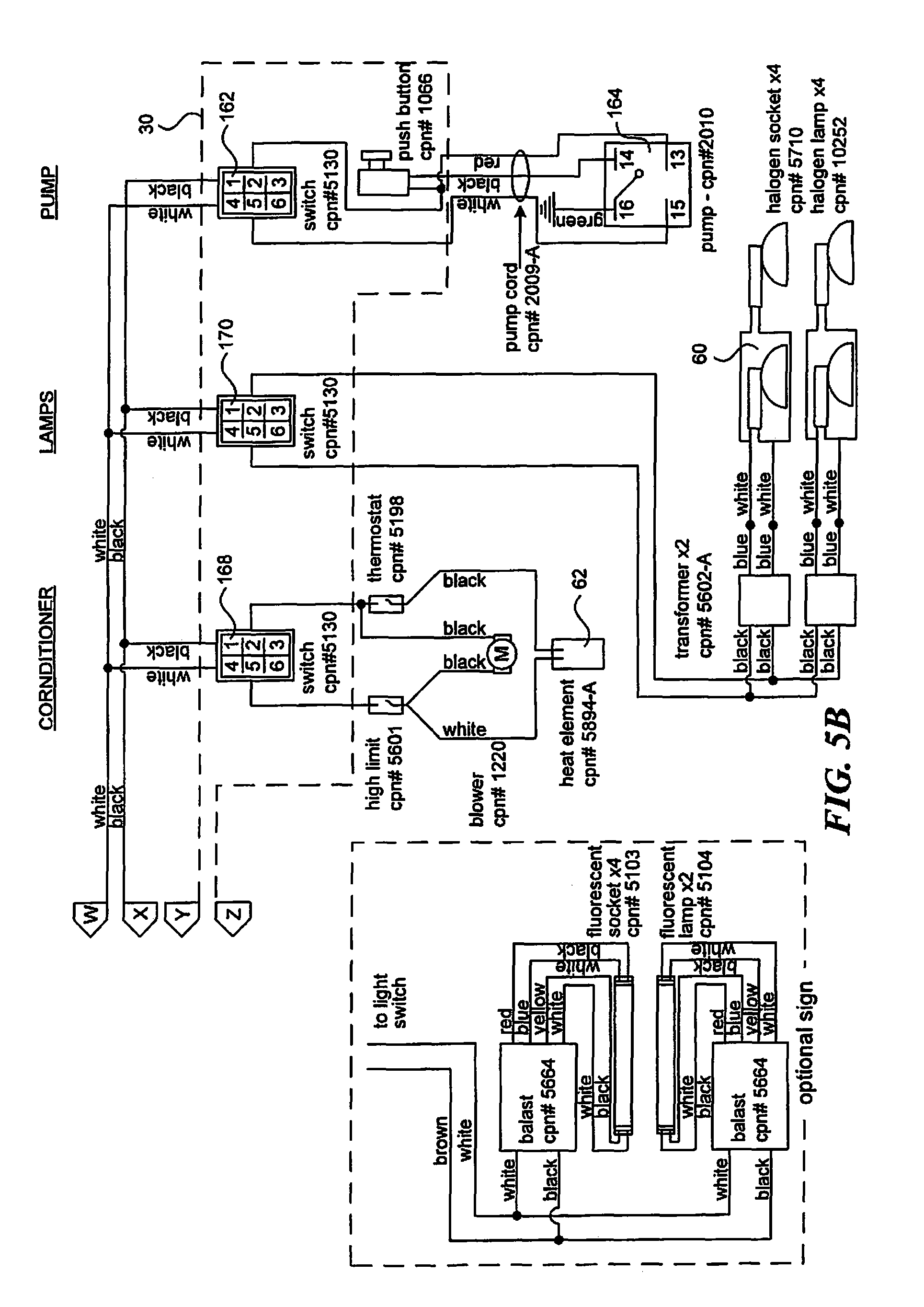
Ansul system wiring schematic. The fire alarm system must also shut down the ansul system as well when it goes into alarm as is there a schematic i can download or look at? Hi, i'm trying to emulate a previous engineer's wiring diagram drawings, and was wondering if anyone has insight on the best way to do it. Automatic ups inverter system wiring diagram (one live wire). For residential and commercial applications.
Wiring schematics and symbolscircuit information • many wiring schematics include numbers and letters near components and wires that may confuse readers of the schematic. Caterpillar 416e blackhoe loader shematic hydraulic system [pdf, eng, 494 kb]. Working and operation of ups connection. Toolmaking and automation qman d.
(1) when utility power is not available from then power supply will continue through the phase wire (note that neutral is already connected) which is connected to the ups from main board. Comparison between relay system and traditional system. All system components shall be securely supported independent of the wiring. This video is the first in a series of three videos bout.
- 2014 Ford Fiesta Fuse Box Diagram
- 2006 Jetta Fuse Box Diagram
- Dot And Cross Diagram For Magnesium Chloride
A wiring diagram is sometimes helpful to illustrate how a schematic can be realized in a prototype or production environment. See more ideas about diagram, electrical problems, repair guide. A schematic is a map of the wiring and current flow through the various components of an appliance. I need to see things sometimes, i'm a little thick with i need help with wiring an ansul micro switch.
Wiring schematic diagram and worksheet resources. And monitoring systems, control systems etc. Understanding the symbols and layout of a wiring schematic will help you test each component so that you can buy the right part to fix the problem. Annunciator wiring schematics and dimensioned display panel illustration shall be provided.
Extension monitor vl‐mwd272 wireless sub monitor vl‐wd613 rear view (non polar) rear view (non polar) dect repeater vl‐fkd2 rear view (non polar) *a total of up to 6 extension monitors and wireless sub monitors can be registered to the main. Ansul systems operate automatically when fire linkages are connected and the tension lever is on. Annunciator wiring schematics and dimensioned display panel illustration shall. Reading guidelines for ac and dc schematics in protection and control relaying (on photo:
I have done a few but the ansul guys always had a schematic. I have receptacles that are supposed to shunt and an. Consult an abyc certified marine electrical professional for system design and circuit protection. It will help others to quickly understand the components and connections involved.
This includes ac schematics and dc schematics and diagrams that prominently feature relaying. A wiring diagram or schematic is a visual representation of the connections and layout of the following reference sections provide installation documents and wiring diagram schematics for maglocks door access system components, kits and. The following basic wiring diagrams show how batteries, battery switches, and automatic charging relays are wired together from a simple single the diagrams below are intended for reference only. Runs of conduit and wiring shall be straight, neatly arranged, properly supported, and installed parallel and perpendicular to walls and.
The wiring on the system has four micro switches with a no, nc, and common contacts. • run stp wiring through the cooling tube and along with the power wiring of the fan. Figure 10 provides an example of the relationship between a schematic diagram (figure 10a) and a wiring diagram (figure 10b) for an air drying unit. Chapter 9 wiring schematics and circuit testing.
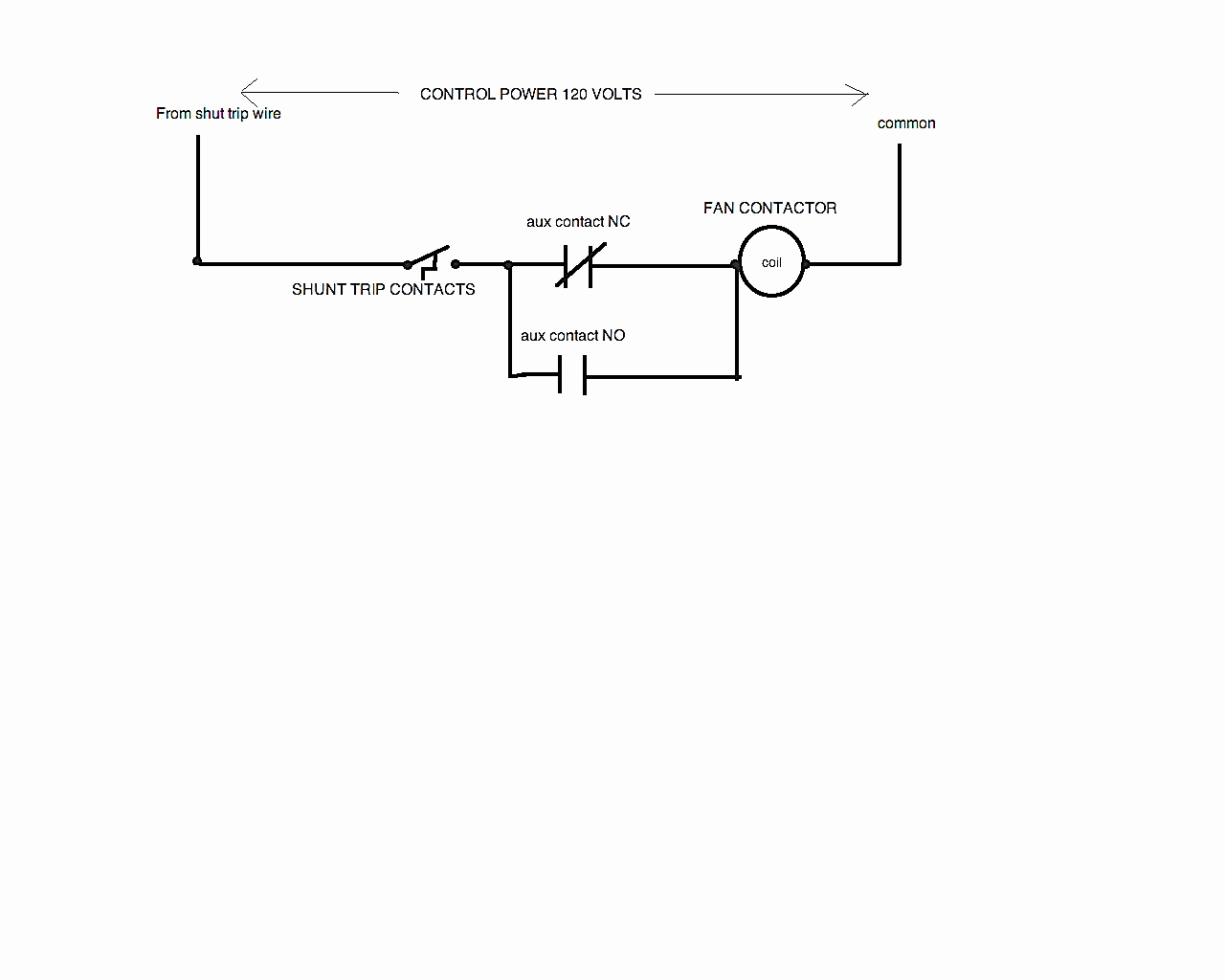
Electrical diagrams and schematics, electrical single line diagram, motor symbols, fuse symbols, circuit breaker symbols, generator symbols. How do i wire this system to do what i need with shunt trip breakers. According the schematic trace color coding developed by jorge menchu, which color of the following colors is used to depict ground when the circuit is complete, open circuit voltage when it is not? Kitchen exhaust pollution control system (12 pages).
C15 cat engine wiring schematics [gif, eng, 40 kb]. Installation schematics and wiring diagrams: • most letters used near or on a wire identify the color or colors of the wire. From an electrical standpoint they are easy.
Video intercom system vl‐swd272 +. Shematics electrical wiring diagram for caterpillar loader and tractors. The following schematics compare the typical ways an msr6r/t safety relay can be applied and the ci safety relay equivalent.

