4 Post Solenoid Diagram

Mini Starter Wiring Instructions Mustang Tech Articles Cj

Diagram Terminal 4 Post Solenoid Wiring Diagram Full Version

Diagram 4 Post Starter Solenoid Wiring Diagram Full Version
Here is the basic wiring diagram for the relay unit.
4 post solenoid diagram. Are you guessing or do you have a rationale for that answer? Don't forget to hook backup any other wires that were. Here is a diagram if you have both solenoids. Replacing a shift solenoid is often costly so you want to make sure that you are not replacing a functional shift solenoid.
If you have one, post it. Circuit diagram of controlling heavy motors. Here is a brief overview of the a solenoid valve is an electronically operated device. I also will be running a transbrake with bump button, so more to figure.
Solenoids can be used to electrically open doors and latches, open or close valves, move and operate robotic. 1) cast iron body with wide moulded passages. If an open or short circuit occurs in any of the shift solenoid valves, the ecm controls the remaining normal shift solenoid valves to allow the vehicle to. Hey club lexus, i need a solenoid diagram for a 92 sc 400 transmission (a341e).
- Old Style 13 Speed Shift Knob Air Line Diagram
- 2007 Hummer H3 Stereo Wiring Diagram
- Troy Bilt 46 Inch Drive Belt Diagram
Solenoid operated directional control valves. In proportional solenoids, the current flowing through the coil is directly proportional to the magnetic field generated. So they are perhaps not as thoroughly understood as they should be, and designers may have a tendency to overlook or avoid. Solenoid valves are highly engineered products that can be used in many diverse and unique system applications.
Im only finding diagrams for the a340e ! P0010/11 which refers to the intake solenoid p0013/14 which refers to the exhaust solenoid. Solenoid valves are usually made up of stainless steel, teflon, and brass materials that have different corrosive and heating properties. Printable graph paper electrical diagram ford tractors engine repair starter motor electronics projects lawn mower wire cleaning.
Don, first, thank you for all your posts on the subject of solenoid issues for the 09a. Therefore, i've posted some camshaft position actuator valve diagrams on this page to help you locate the individual components. Start date jul 24, 2016. Shifting from 1st to o/d is performed in combination with the on and off operation of the shift solenoid valves sl1 and sl2, which are controlled by the ecm.
Connect the positive post of the battery to the large post on the starter. I have found some diagrams in here, but are all for the dominator. I could not find a diagram that showed how to test the tcu on a 97 up cherokee, so i did the next best thing. I got a call from my wife on her way to work that the check engine light came any chance you have the same solenoid diagrams for that model?
The single relay controlled starter solenoid wiring diagram is as shown in the following picture. For the solenoid that is mounted on the starter: The designer can estimate armature position by knowing the current that is flowing through the solenoid. How do you expect us to help you if you don't show your work?
Solenoid actuators work by attracting a movable ferrous armature into the center of the solenoid coil when energized, the force of this attraction working to actuate a small valve mechanism. Connect smaller neutral safety switch/ignition switch wire to the smaller post. In this tutorial we will show you how to use a nodemcu and a relay board that can be used to control things like solenoid valves. Cetop 03 p max 350 bar q max 75 l/min.
Solenoids are not particularly exotic in their capabilities, and they are not as common as two other members of the electromechanical family, namely, relays and motors. Массив пинов соленоидов int solenoids[] = {solenoid_1_pin, solenoid_2_pin, solenoid_3_pin In this guide, you will find everything you need to know about transmission shift solenoids, how to locate the problem and how to replace the parts.
Gallery of 4 Post Solenoid Diagram
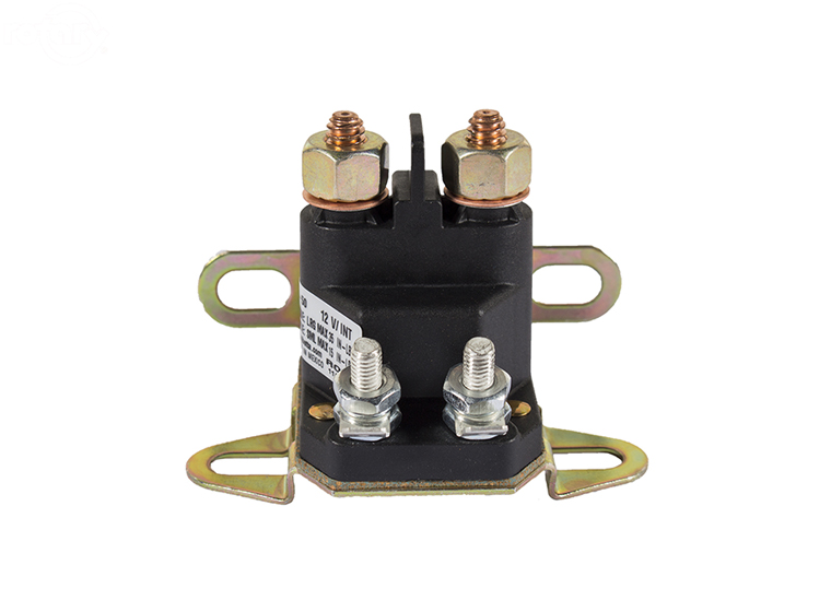
Universal Starter Solenoid 4 Pole 12 Volt

Diagram 4 Post Solenoid Wiring Diagram Ez Go Full Version Hd
Diagram 3 Post Starter Solenoid Wiring Diagram Full Version
Briggs Amp Stratton 4 Pole Starter Solenoid 5410k

Diagram Cole Hersee 4 Post Solenoid Wiring Diagram Full

Diagram In Pictures Database Cole Hersee 4 Post Solenoid
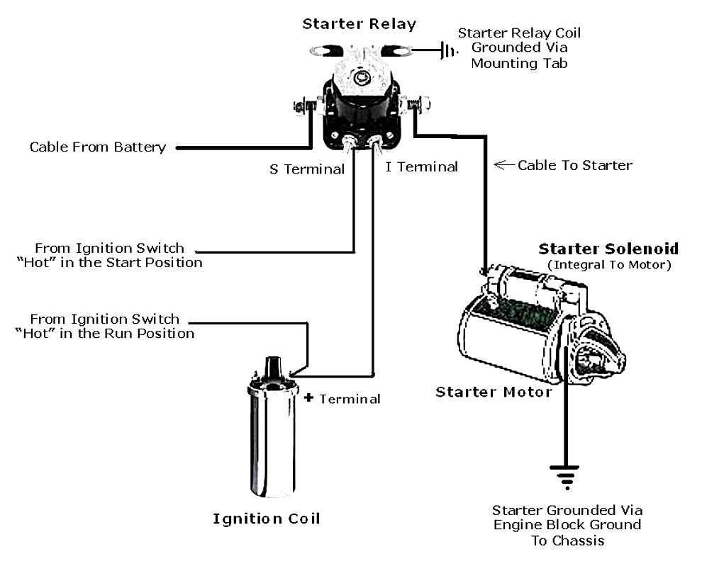
Diagram Eagle 4 Post Wiring Diagram Full Version Hd Quality

4 Post Solenoid Wiring Diagram Full Version Hd Quality Wiring
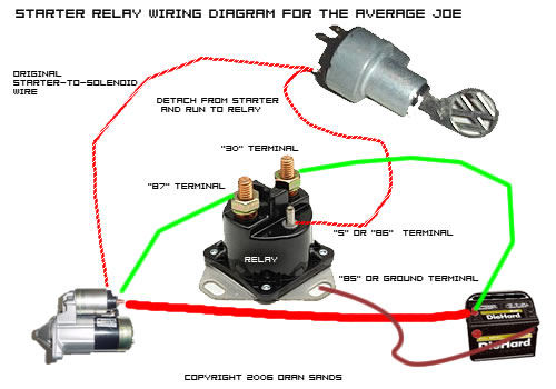
Diagram 4 Post Solenoid Wiring Diagram Full Version Hd
4 Wire Solenoid Diagram Gota Wiring Diagram
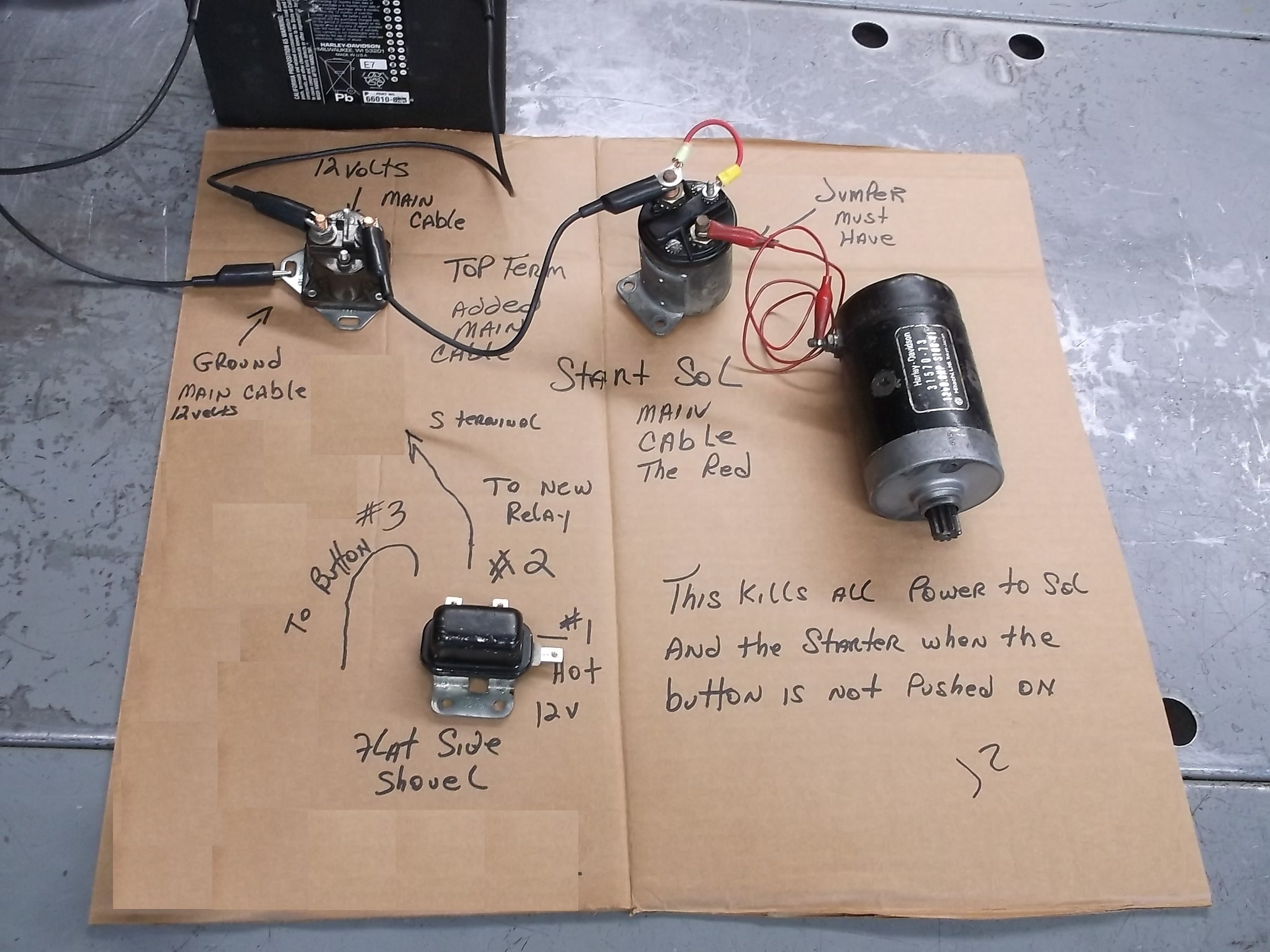
Diagram 4 Post Starter Solenoid Wiring Diagram Free Picture
Diagram 6 Post Solenoid Wiring Diagram Full Version Hd

Diagram 4 Post Solenoid Diagram Full Version Hd Quality

Diagram 4 Post Winch Wiring Diagram Full Version Hd Quality

Wiring Diagram Mtd Lawn Tractor Wiring Diagram And By Starter

Diagram 4l60e Solenoid Diagram Full Version Hd Quality

Diagram 4 Post Starter Solenoid Wiring Diagram Free Picture
