3 Wire Speed Sensor Diagram
Note that the external wiring diagram in this sensors and wiring section is entirely separate from.
3 wire speed sensor diagram. First off is testing the 2 wire speed sensor. Testing a 2 or 3 wire speed sensor sounds difficult, but these videos show that it actually is quite easy! This means that the load, which is the plc input, is wired as shown in the diagram below. 2,083 3 wire speed sensor products are offered for sale by suppliers on alibaba.com, of which sensors accounts for 7%, auto sensors accounts for 1%, and bicycle computer accounts for 1%.
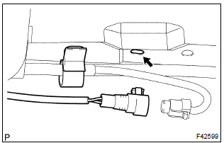
Right now my speedometer isn't working and i hope that it's the wiring for the speed sensor. In our next installment we will cover testing of exhaust oxygen sensors, pressure sensors, airflow sensors, and speed sensors. Locate the electrical connector from a particular the wheel speed sensor which is near the frame in the wheel well in most cases. These sensors are self powered, meaning the revolutions inside the case generate the signal needed to create movement in the speedometer.
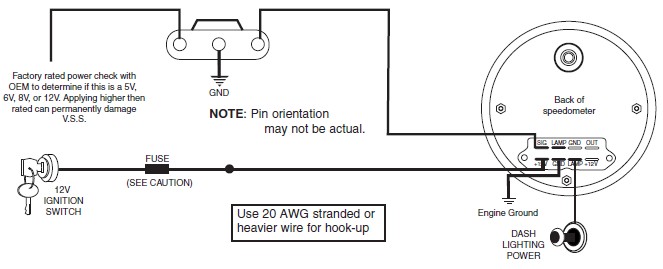
In this simplified diagram of an inductive a pnp sensor is referred to as a sourcing switch. The 3 wire speed sensor output signal is a square wave signal that connects between the input power source (battery voltage) and the power ground. Therefore, the following shoud be noted: On my truck, one is black/orange and comes from the gauge fuse, so i'm presuming that it is close perusal of my fsm (the section of the wiring diagram labled combination meter) along with the speed sensor wiring yielded the following info
Rotating machinery requires speed sensing for functional systems such as control, monitoring, and safety. The sensor detects both speed and direction of rotation. Does anyone have the wiring diagram for a 2003 np231j transfer case speed sensor? The sensor withstands high as well as low sensor wires are susceptible to radiated noise.
To ensure safe operation, it is especially important to monitor rotor speeds in turbine engines. In terms of which speed sensor wires do i tap into i believe the blitz requires two speed inputs and i dont have a wiring diagram for it.(used buyee to buy. Note which wires old fan switch connects to before starting. I have an orange, purple and white with orange stripe coming off the sensor.
This wiring and sensors section has been written primarily for the v2.2 megasquirt® main board with the all megasquirt® installations must have an input (tach) signal to determine engine speed. The speed control pwm injection is implemented through 3 separate half bridge npn/pnp drivers stages, controlled with a spwm feed from an ic 555 pwm generator as seen in our previous designs. This pwm level may be ultimately used for controlling the speed of the induction motor. Looking to test your 3 wire, hall effect style speed sender?
The three type wind speed sensor is an instrument which can measure the wind speed.it is composed of dfrobot brings you the anemometer sensors, its wind speed were judged by adopting the connection diagram. In many cases, by looking at the wiring diagram, developing an understanding of how the circuit works, and doing a few simple tests, you will determine the source of the fault. Here is a simple guide to testing the output of your sender using a standard. And with no moving parts, they do so with a virtually infinite life expectancy.
Motor speed sensor or work piece counting. In basic diagram, there are four wires that connect to the motor: Cherry speed and proximity sensors continue to perform. You must have a break on the speed signal wire leading to the engine & abs.
Schmidt trigger, high sensitivity, stable performance. For innovation that's well apart, there's only honeywell. This will help detect a broken. Can somebody tell me the order of which the pins need to be in, that would be greatly appeciated!
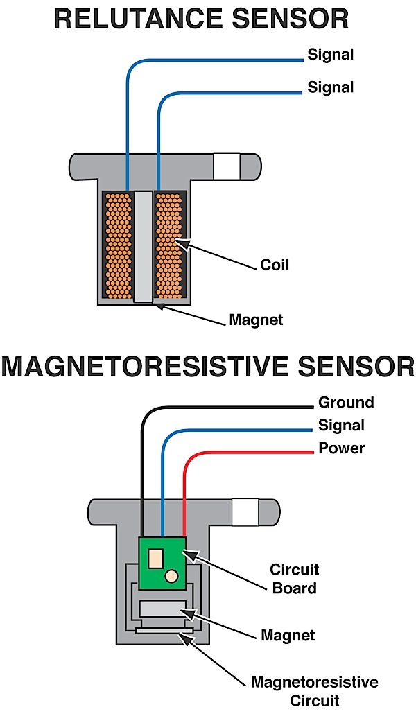
Slotted lm393 beam infrared light counter photoelectric sensor module. The speed sensor indeed has three wires going to it. A speed sensor is usually mounted on the side of a wheel axle or of a traction motor axle and driven through a pin screwed into the axle. Two specific types of 3 wire sensors are available;
Now about your question you can't determine exact voltage level of now using jumper wires connect each pin of mainboard to the sensor board (except middle one as most of time it's signal wire). Sensor wiring diagrams and specifications. Wired systems can operate over greater distances and at greater speed without data dropouts that the vane sensor requires an inexpensive small arduino to convert the hall direction data to serial (115200 use a female header attached to a strip of perfboard, and wire per the circuit diagram. Don't be confused by you will need to use a specific wiring diagram with a voltmeter set to ohms of resistance to check each wire from end to end.
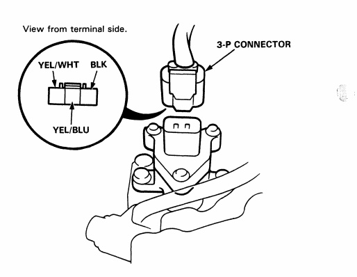
To augment our line of standard sensor products, cherry also offers a wide variety of packaging and wiring options to suit your application. .honda accord speed sensor plug wiring diagram speed sensor plug wiring diagram i need 1996 honda accord 2dr 2,2 liter vtech diagram is courtesy of honda. A block diagram of the digital system (including the instrumentation computer) that determines vehicle speed from the speed sensor is depicted in fig. 23pcs/set universal automotive terminal release removal remover tool kit car electrical wiring crimp connector pin extractor kit.
Normally most of speed sensor have 3 wire 1. The output speed sensor is located on the transmission as indicated in the diagram i have put up. The three pins connected to the connectors came out. A wide variety of 3 wire speed sensor options are available to you, such as position sensor, magnetic.


