Toyota 3 Wire Speed Sensor Diagram
Rob elliott,.99 corolla wiring diagram speed sensor.
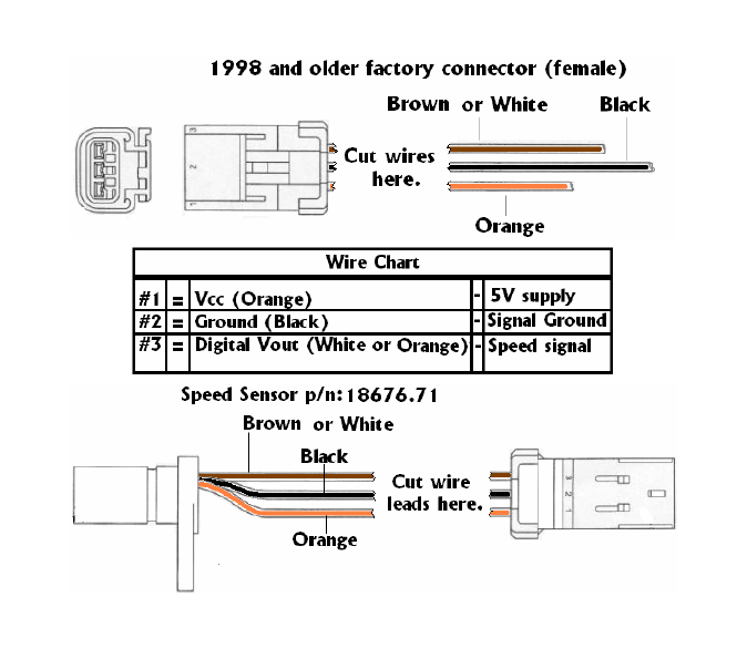
Toyota 3 wire speed sensor diagram. This pwm level may be ultimately used for controlling the speed of the induction motor. Toyota t100 1996 manual online: Since the 3 wire sensors are use our dual fan wiring diagram and guide to make sure you properly wire your fans to your thermostat. The speed sensor detects the wheel speed and sends the appropriate signals to the skid control ecu.
Most toyota 3 wire speed sensors have the. Does anyone have the wiring diagram for a 2003 np231j transfer case speed sensor? In many cases, by looking at the wiring diagram, developing an understanding of how the circuit works, and doing a few simple tests, you will determine the source of the fault. Abs brake wheel speed sensor testing.
Color code wire i do not know?… read more. How to test 4 wire throttle position sensor on 2003 toyota tocoma 3.4? Note which wires old fan switch connects to before starting. Control.pdf speed sensor.pdf starting system.pdf tempature sensors.pdf tps switch.pdf transtors.pdf.
- 2016 Silverado Trailer Fuse Location
- 2004 Cadillac Deville Radio Wiring Diagram
- Silverado Front End Diagram
Sensor, speed uses magnetic impulses to open and close a switch to create a signal for activation. This wire only connects to these components for each item in your list, identify the wires you need to connect from the list and wiring diagram below and your vehicle wiring diagram. I have an orange, purple and white with orange stripe coming off the sensor. Some things to think about 125.
The speed control pwm injection is implemented through 3 separate half bridge npn/pnp drivers stages, controlled with a spwm feed from an ic 555 pwm generator as seen in our previous designs. Right now my speedometer isn't working and i hope that it's the wiring for the speed sensor. Toyota part number are indicated. 99 corolla wiring diagram speed sensor 99 corolla wiring diagram speed sensor available in formats pdf, kindle, epub, itunes and mobi 5.
This type of sensor has an electronic circuitry built inside and thus provides a constant voltage pulse regardless of the speed. I had to pry open some flexible plastic split conduit to reveal the wire, and i chose to cut some of the conduit. I turned the sensor slightly until it read 12v and then tapped the signal wire to ground and then the needle moved on the speedo. In basic diagram, there are four wires that connect to the motor:
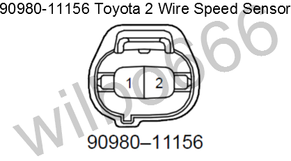
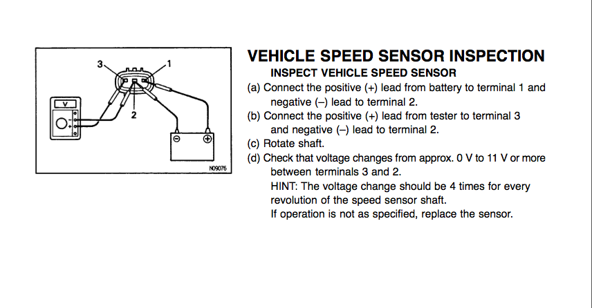
Then, i wired yellow and blue/red onto the gm speed sensor and only 1 wire from both the gm and toyota sensor carry the signal, regardless of the diagram contradicts that info. This sensor detects the rotation speed of the counter gear. The speed sensor outputs 4 pulses (high to low voltage transitions) for each speed sensor revolution. Not all of the above part numbers of the connector are established for the supply.
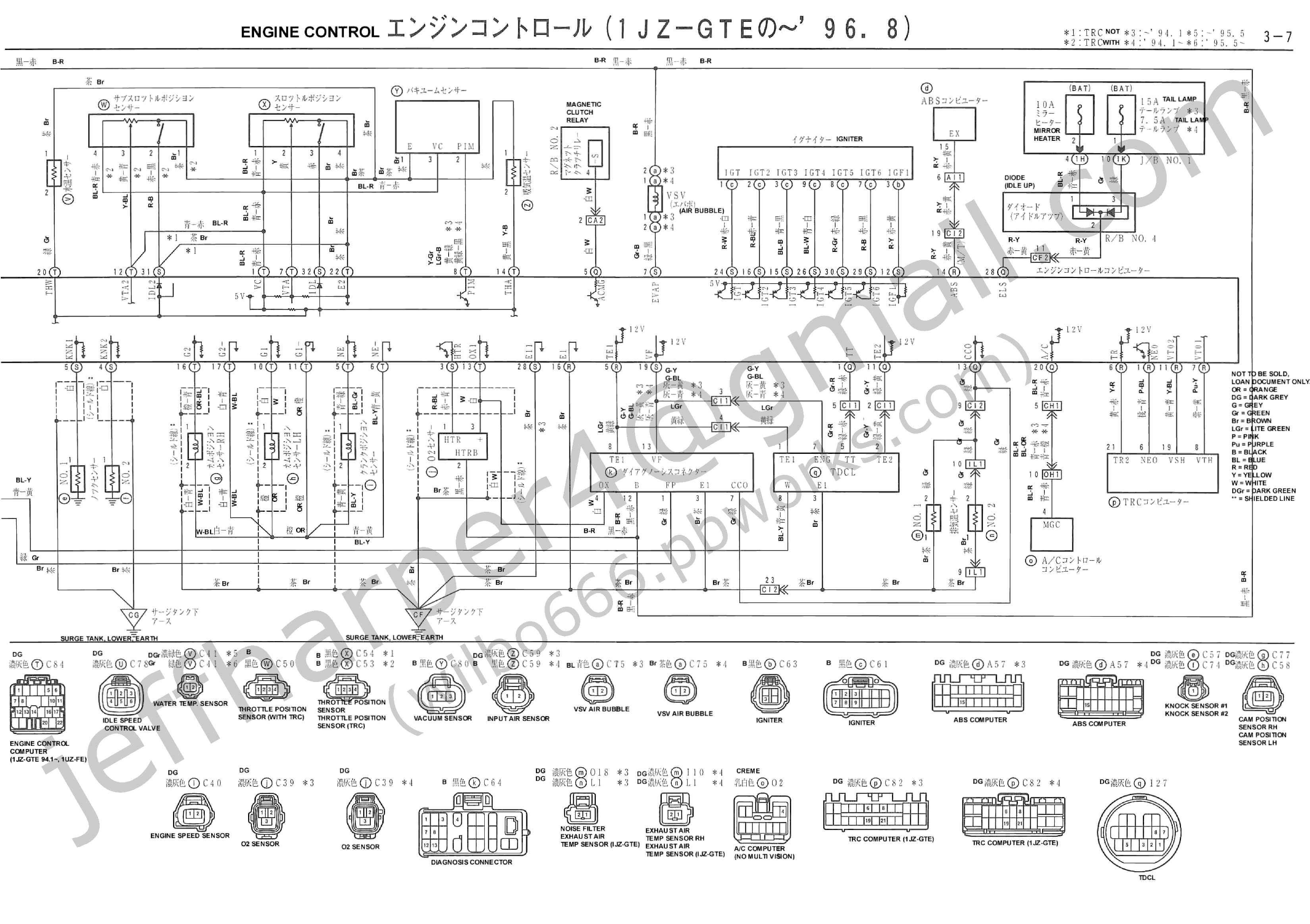
Note that the external wiring diagram in this sensors and wiring section is entirely separate from, though similar to, the relay board. Are those picture from a supra service manual. The speed sensor indeed has three wires going to it. The sensor is also sensitive to the.
The wire labeled vref is the +5v voltage source for the map sensor and the tps sensor. The 3 wire speed sensor output signal is a square wave signal that connects between the input power source (battery voltage) and the power ground. If possible can you post the 1974 fj40 wiring diagram? Testing a 3 wire (hall effect) speed sensor is nearly as simple.
The 3 wire speed sensor is externally powered, so you will need a power source of some form. Components removal disconnect cable from negative battery terminal caution: The speed sensor wire that you want to tap into is the gray/blue wire from the abs ecu in the right kick panel on pin 14. The three pins connected to the connectors came out.
The basic tps requires three wires. Using the intelligent tester to read the data list allows the values or states of switches, sensors, actuators and other items to be read without removing any parts. Provides circuit diagrams showing the circuit connections. Free repair manuals & wiring diagrams.
Please be sure to read the instruction manual for the the rev speed meter requires both the instruction manual and the wiring diagram for proper even though a vehicle is listed in this manual. On my truck, one is black/orange and comes from the gauge fuse, so i'm presuming that it is close perusal of my fsm (the section of the wiring diagram labled combination meter) along with the speed sensor wiring yielded the following info I tried to wire my 3 wires and it won't work at all. Five volts are supplied to the tps from the vc terminal of the ecm.
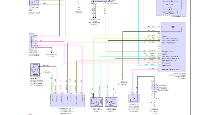
Speed sensor rotors have rows of alternating n and s magnetic poles (for 2wd) or 48 serrations (for awd).
