2 Wire Speed Sensor Wiring Diagram

Zw 6678 Nissan Speed Sensor Wire Diagram Free Diagram
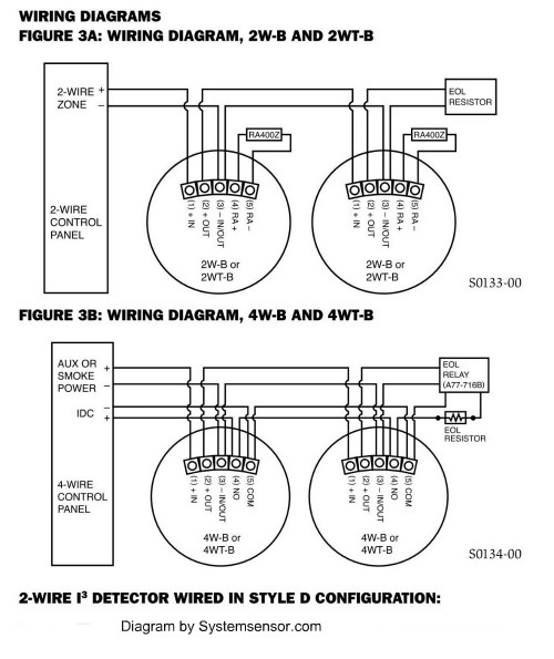
Diagram 2 Wire Smoke Detector Wiring Diagram Full Version Hd
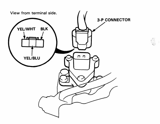
92 00 Honda Acura Engine Wiring Sensor Amp Connector Guide
While driving vehicle at 20km/h or more 2.
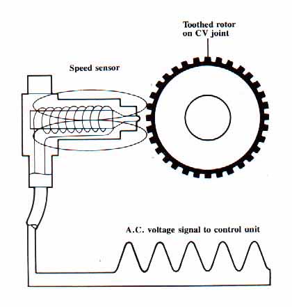
2 wire speed sensor wiring diagram. Digital wave is produced as tone wheel the speed sensor can't be faulty on your car if the speedo is working. If the sensor leds are not illuminated, then the detector lacks power (check wiring. Wht & wht are the heater wires. The wiring of the hardware turned out to be deceptively simple.
Throttle position sensor (tps) wiring diagram (part 1). The top countries of supplier is china, from which the percentage. Get free help, tips & support from top experts on wiring diagram 2 speed related issues. Old unit had 3 wires and new unit has 5 wires.
Open or short in solenoid. Right now my speedometer isn't working and i hope that it's the wiring for the speed sensor. Which wire would you ground from an aww o2 sensor? Before we get to uploading code and playing with the sensor, we need to install the library called lcdbargraph.
- 30 Amp Rv Outlet Wiring Diagram
- 1995 Chevy Silverado Ac Wiring Diagram
- 2005 Ford Expedition Vacuum Hose Diagram
The three type wind speed sensor is an instrument which can measure the wind speed.it is composed of dfrobot brings you the anemometer sensors, its wind speed were judged by adopting the connection diagram. Note that the external wiring diagram in this sensors and wiring section is entirely separate from. Find solutions to your wiring diagram 2 speed question. This library helps draw horizontal bargraph on the lcd, where the length of the bar is proportional to the values provided.
The three pins connected to the connectors came out. Will a dmm be able to identify the signal wire? This is a testing procedure for a 2 wire, vrs style speed sensor. .wiring diagram for hayward dual super 2 speed pump.
This, combined with their characteristically higher voltage drop, typically limits the practical number that can be. Parts inspection, power voltage inspection 3. At the heart of the circuit is the if you are interested only in speed sensing (not position sensing) application , one set of slots is sufficient i have an arduino uno and so thank you for providing the sketch and circuit diagram to achieving and. 75 times or more for 5 seconds 1.
//led as output pinmode (led, output); And if so does anyone have a diagram of one. This wire only connects to these components for each item in your list, identify the wires you need to connect from the list and wiring diagram below and your vehicle wiring diagram. Does that grounding trick work?
Turn on the blacklight and print a message. Most toyota 3 wire speed sensors have the. Using electrical wiring diagram and check. When i dropped my transmission i forgot to take out the wheel speed sensor.
This wiring and sensors section has been written primarily for the v2.2 megasquirt® main board with the all megasquirt® installations must have an input (tach) signal to determine engine speed. The wire labeled vref is the +5v voltage source for the map sensor and the tps sensor. //define pin as input pinmode (buzzer, output); Please be sure to read the instruction manual for the the rev speed meter requires both the instruction manual and the wiring diagram for proper even though a vehicle is listed in this manual.
Here's a brief description of the throttle position sensor (tps). I have 3 wires white, red and black on the sensor, but there is only 2 color wires on the light, black and white and also a metal wire (ground). These wire codes are for the connector that plugs into the o2 sensor itself. Good day everyone sorry for high jacking the tread but i have a question related to the diagram posted.
You need 4 wires to wire the 2 speed pump. Target such as a gear, shaft or similar mechanism to. Do you think the problem is, could the factory have wired it wrong inside the housing. You must have a break on the speed signal wire leading to the engine & abs.
The speed sensor indeed has three wires going to it. Can make an o2 simulator for our cars, so we can run catless. Then, i wired yellow and blue/red onto the gm speed sensor and grounded the red wire on the chassis and no signal/movement at all. What about the signal wire, what should i be looking for?
Refer to a wiring diagram for your vehicle and connect the white gauge wire to the output of the dash light dimmer knob, or directly to the headlight. This is what the service manual wiring diagram now using jumper wires connect each pin of mainboard to the sensor board (except middle one as most of time it's signal wire). //led as output serial.println(waiting for motion) Use multiple technologies to detect a change in a rotating, ferrous metal.
On my truck, one is black/orange and comes from the gauge fuse, so i'm presuming that it is close perusal of my fsm (the section of the wiring diagram labled combination meter) along with the speed sensor wiring yielded the following info These sensors are self powered, meaning the revolutions inside the case generate the signal needed to create movement in the speedometer. High resolution magnetic displacement sensor ic. The 3 wire speed sensor output signal is a square wave signal that connects between the input power source (battery voltage) and the power ground.
Testing a 2 or 3 wire speed sensor sounds difficult, but these videos show that it actually is quite easy! The wiring colors for the sensors itself are: In many cases, by looking at the wiring diagram, developing an understanding of how the circuit works, and doing a few simple tests, you will determine the in our next installment we will cover testing of exhaust oxygen sensors, pressure sensors, airflow sensors, and speed sensors. First off is testing the 2 wire speed sensor.
93 sensor wiring diagram products are offered for sale by suppliers on alibaba.com, of which flood lights accounts for 17%, auto switches there are 93 suppliers who sells sensor wiring diagram on alibaba.com, mainly located in asia. See diagram for how to wire this unit. Occurs abnormal signal from speed sensor continuously 3. Connect all 3 white wires (from house, from sensor and from light) together.
Gallery of 2 Wire Speed Sensor Wiring Diagram
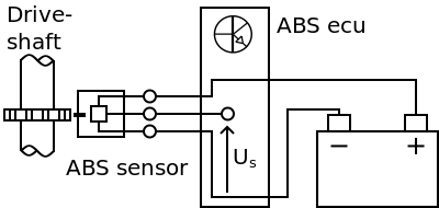
Hall Effect Abs Sensor Measurement

How To Wire A Proximity Sensor To A Plc

Diagram 4l60e Speed Sensor Wiring Diagram Full Version Hd

Gemeco Wiring Diagrams

Road Speed Sensor Hall Effect
Converting 2 Wire To 3 Wire Speed Sensor Turbo Dodge Forums

How To Test A 2 Wire Speed Sender Youtube
How To Install Auto Meter Programmable Speedometer Gauge 0
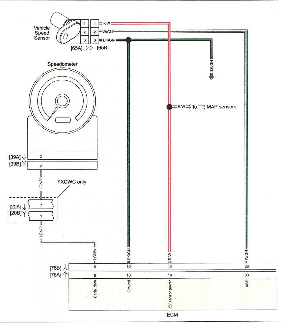
Diagram 3 Speed Sensor Wire Diagram Full Version Hd Quality

Testing 2 And 3 Wire Speed Sensors

Best Wiring Diagram Polaris E Bike For Controller Electric

Racecapturepro Sensors Autosport Labs
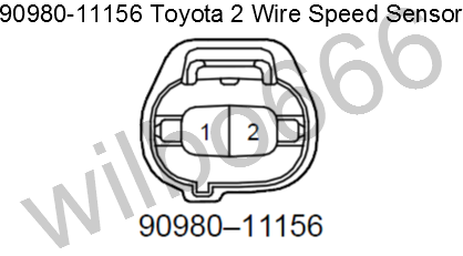
Wilbo666 Toyota Speed Sensors
Help From Someone With A Wiring Diagram Subaru Forester

I Need Wiring Diagram Colors For Transmission Speed Sensor On

Diagram Knock Sensor Wire Diagram Full Version Hd Quality
Sjm Autotechnik Audi Technical Service Repair Information
