Wiring Diagram For Push Button Start
Push the button and watch the servo move to a different angle each time.
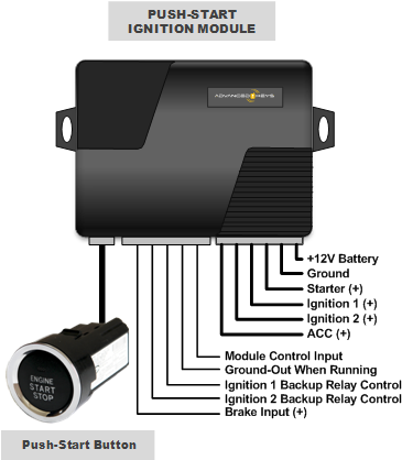
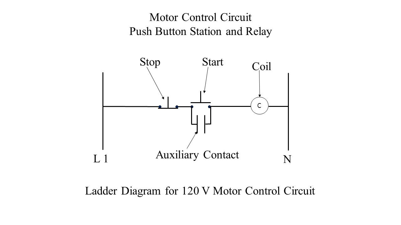
Wiring diagram for push button start. The drawing for vfd start stop wiring diagram from panel.vfds are called as variable frequency drive or variable voltage variable frequency drive. Push button circuit wiring diagram 0 0 4 reference point identified on starter corresponds with number shown in push button station wiring. Wiring diagrams/charts were taken from commandocaralarms.com: I have brought my jeep wrangler unlimited into the 21st century.
We?ve barely started to cover the huge variety of maintained. In the wiring diagram, it says the tag for the plc input that the push button is connected to is 300u2.1. Start date dec 27, 2018. Here plc command is shown as no push button in the above diagram.
Typical wiring diagrams for push button control stations 3. There are several pole and throw configurations for pushbutton switches. This video in single push button on off wiring diagram. Typical wiring diagrams for push button control stations 3 genera information at each circuit is.
- 1995 Ford Ranger Wiper Wiring Diagram
- 1998 Chevy 1500 Brake Light Wiring Diagram
- 2007 Kia Sportage V6 Serpentine Belt Replacement
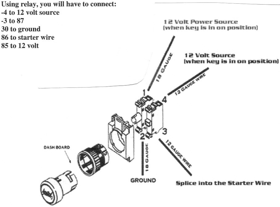
For the wiring up the servo, you say in your description (and the code) to hook up the blue wire to pin 3 of the arduino, but in your wiring diagram. Let's start by wiring up the components on a breadboard. Instructions for wiring in push button to starter switch so i installed a push button start by tapping into the red/lt. This applies to a sedan since the coupes have the mirror controls in.
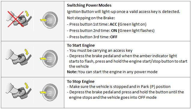
Push start buttons and toggle switches allow you to operate a vehicle with the push of a button. In this sample, we connect a push button to your raspberry pi 2 or 3, up squared*, or the dragonboard 410c and use it to control an led. Installation support for gallo technologies push button start systems. I borrowed that switch picture as.
Push start button x1 pke antenna: .push the start button and nothing happens, last year i had the starter rebuilt,and it worked great till the end of the season. Find solutions to your push button starter wiring diagram question. X1 3 color (orange, white, yellow) gwr wire x1 or (shock method is as right diagram:
X2 6p ignition wire harness: These are the tags for the plc inputs and so this is how easy it is to read the wiring diagram for a control panel. I hope you enjoyed making this project and learned something along the way! Pushbutton switches are mechanical switches defined by the method used to activate the switch.
The application is loaded to make it easier for you to learn about electricity that helps you in knowing the electrical circuit. Installation instructions, vehicle wiring diagrams and help links for our gtstarter push button engine start systems. These can be found, for example, in stomp switches on guitar effect pedals. This application contains the start stop wiring diagram push button.
The application is loaded to make it easier for you to learn about electricity that helps you in knowing the electrical circuit. In this servo control push button project, the clockwise and anticlockwise movement of the servo shaft is controlled by two push buttons.how to use a servo with arduino.the control switches are connected to the digital pin.speed of the servo can be controlled by adjusting the time.servo moves. Its based on ones that other 8th gen users have made but i simplified it. Now i'm not even getting a click from the relay under the seat.
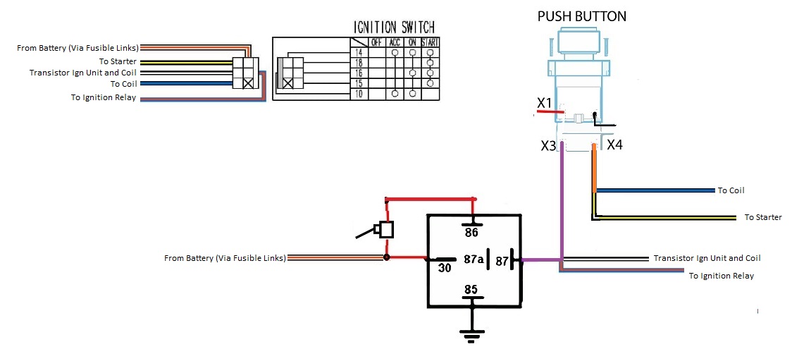
Wire a push button start i need help on wiring my push button start i want to wire everything else to toggle switches the only thing i want to use my ignition how to wire a push starter very easy lostfart. In hindi ,youtube me channel name (khatu shyam plc program and shyam plc program.) all video used. It goes exactly the same for the other switches that we have here as well. I followed the diagram from.
This is the basic wiring diagram that i used. Blue wire going into the harness on top of the steering column, and taking the 12v power required from. When we press push button, relay should be on, it means we use normally open type push button because when we press this switch supply goes forward. With this sort of an illustrative manual, you are going to have the ability to troubleshoot, prevent, and complete your projects without difficulty.
Pushbuttons or switches connect two points in a circuit when you press them. Though these two devices are similar in their use and installation, the process varies push the switch wire into the hole and connect it to the power supply wire of the vehicle using a terminal connector. The activation method is typically in the form of a plunger that is pushed down to open or close the switch. This application contains the start stop wiring diagram push button.
We can replace no push button with plc command. This application contains the start stop wiring diagram push button. First i wired up the harness. As promised to those following my posts.
What would a wiring diagram for that look like?
