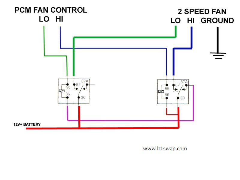
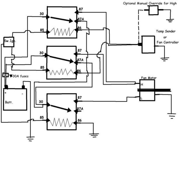
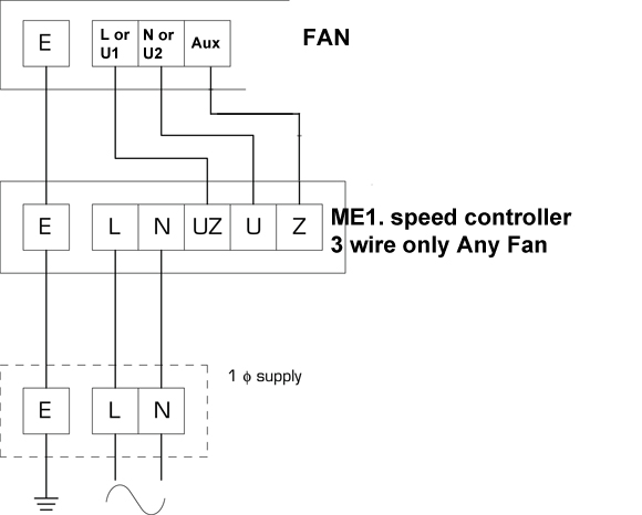
Wiring Diagram For 2 Speed Fan Motor
We can control the speed of the dc motor by simply controlling the input voltage to the motor and the most common method of doing that is by using pwm signal.
Wiring diagram for 2 speed fan motor. Checking wires, connectors and related components. They are commonly used in portable power. Universal motors have high starting torque, can run at high speed, and are lightweight and compact. I would like to add a separate switch next to this box, bring power into switch.
The motor will have three wires; The fan is not turning on low speed if the engine is on, even if it reaches the heat indicated. Furthermore, make sure you follow the wiring diagram for the heat pump to terminate the new condenser fan. Do i need to visually see where on the motor the wires go?
The circuit diagram of dc fan motor speed controller regulator circuit using 555. Diagram 1 information for wiring diagrams diagram 2 starting, charging, horn diagram 3. Wiring diagram for two speed moto explained. In this post i am gonna to tech you about ceiling fan speed control wiring diagram, from which you easily learn fan speed regulating speeds.
- 2002 Cadillac Deville Stereo Wiring Diagram
- 2005 Dodge Ram Brake Light Wiring Diagram
- 2002 Chevy Silverado Fuel Pump Wiring Diagram
The circuit is built around timer 555, which is wired as an astable multivibrator. I will probably strip the housing off, but i don't. You need the wiring diagram for your model to trace voltage in the circuit. Electric motor run speed side you can also obtain a wiring diagram for your air handler brand, model, serial number from the manufacturer, or give us that information and we'll help.
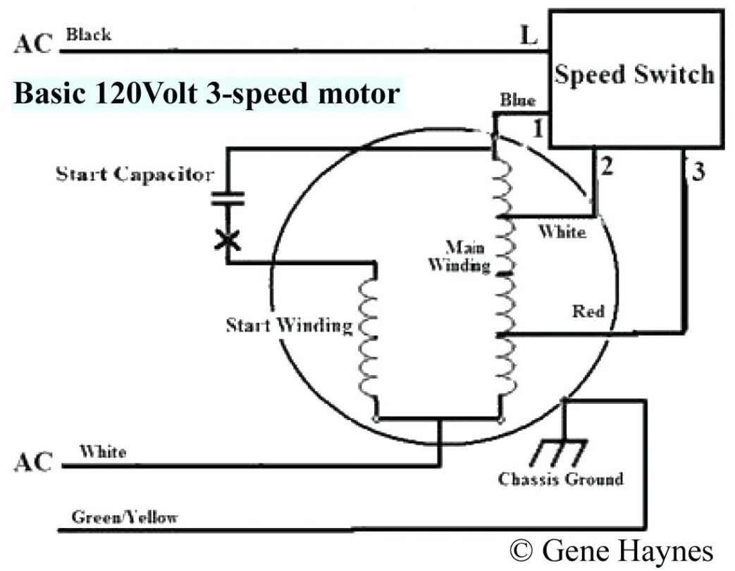
There is a short in the circuit. How to test the cooling fan motor. Ceiling fan speed control wiring diagram with speed control switch, fan motor, capacitor and supply for low, med and high speeds. Additionally, some motors have more than one speed and will need to be wired properly to achieve the proper speed for the control settings.
I'm having a hard time figuring out whats going on in there just from resistances. Heavy duty steel or cast iron frames; There are three input pins for each motor, input1 (in1), input2 (in2), and enable1 (en1) for motor1 and input3, input4, and enable2 for motor2. Dynamically related searches for 2 speed fan motor wiring diagram 2 speed electric motor schematictwo speed motor wiring diagramfan motor wiring.
3ø wiring diagrams diagram dd1. This unit needs to be wired in conjunction with a suitable flasher unit and brake light switch. Note which wires old fan switch connects to before starting. Fan motor driving circuit shown as a simple fan motor driving circuit, which is mainly from the power circuit fan power equipment traditional control methods is through manual or relay control, there is the problem.
Electric motor wire marking & connections. This enhances and quickens the defrost cycle. The duty cycle describes the amount of time the signal is in a high (on) state as a percentage of the total time of it. From left to right first 2 wires tach coil(speed regulating).
Can anyone refer me to a wiring diagram of the guts of this motor? Following is the schematic diagram of a dc motor, connected to the arduino board. Capacitor c1 is connected in parallel to the fan to stabilize its speed. Often times it is no more complicated than the w.
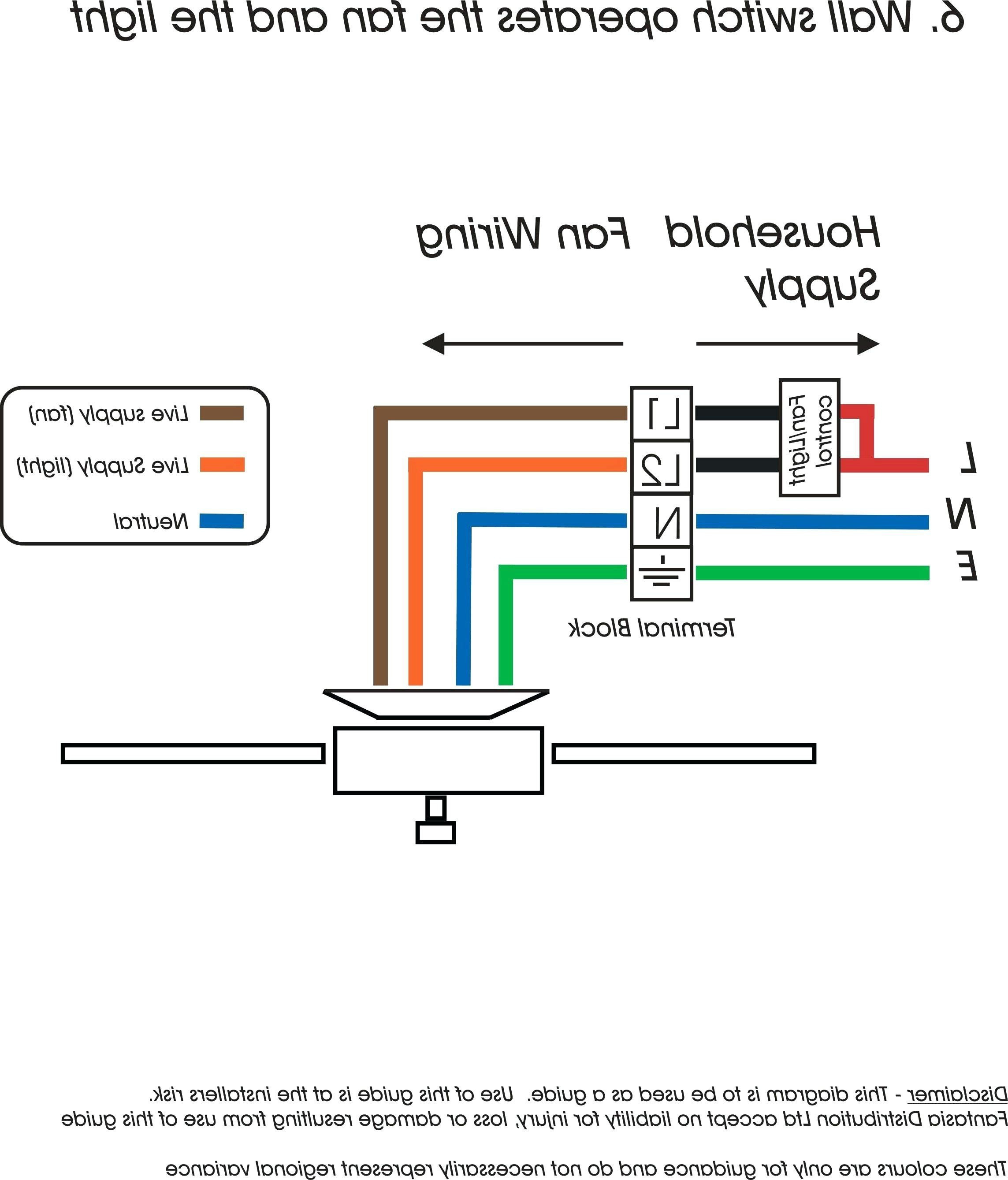
It is a 3 speed motor (d1036) that's replacing the original 4speed motor that was 20 years old or so. Cheers max, the fan housing does have a sticker on with a wiring diagram but gives no colours for the wires. Full color ceiling fan wiring diagram shows the wiring connections to the fan and two switches. 24 egr valve 30 air cond.
The model number on it is logik then the highest resistance is the lowest speed. However, with only two wires, a tach signal is not readily available. Using this fan speed controller circuit you can control the speed of 12v dc fans used in cars. Wiring diagram for mastercool evap 2 stage unit i need to find a wiring diagram for a mastercool evap cooler that has the i had a condenser (outdoor) fan go bad, and it wiped out the control board, the power supply.
Requires hole 14.5 mm diameter. Correct wiring for a ceiling fan switch in a shop. In this motor wiring diagram we can see the key components and the wiring of an universal motor: Inside all motors are coils of wire call windings.
In basic diagram, there are four wires that connect to the motor: Like, subscribe and don't skip the. See how to install & wire up an air conditioner compressor, blower motor, or fan motor hard starting capacitor. Find solutions to your wiring diagram 2 speed cooler controller question.
One ground and two hot wires (one. The first motor control diagram can be much simplified by using a dpdt switch for the motor reversal operation, and by using an emitter follower transistor i build this speed controller, it works for small motors like 775, but when l connect to a car radiator fan motor, it blows off probably the if(worked for. Power and control circuit for 3 phase two speed motor.


