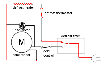
Walk In Cooler Defrost Timer Wiring Diagram
They turn on the defrost system at regular intervals how they can fail over time, the timer motor, motor bearing, or reduction gears on electromechanical timers can wear out.
Walk in cooler defrost timer wiring diagram. 13 paragon universal defrost timer (udt) why do i need a defrost control? See paragon defrost timers with explanation of defrost cycle. Place one of the multimeter's probes on the common terminal. Signs of a problem can include
Larger image dip switches for voltage. Modern, state of the art refrigerators use solid state circuitry to control the defrost cycle, but entry level refrigerators as well as older refrigerators use a timer to control the defrost system. Set the multimeter as instructed above. When i was a little unsure about hooking those defrost timers up, where the timer motor wire went , #1 terminal or # 2 terminal.
13:24 ulises palacios 6 787 просмотров. A wide variety of defrost timer wiring 100 pieces (min. Resources/ manual dtav40 sell sheet with model numbers dtav40 sell sheet and wiring diagrams dtav40 installation and instruction manual wiring changeover for paragon paragon. Dtav40 defrost timer with icubetm module.
- 2004 Ford F150 Vacuum Hose Diagram
- 1999 Dodge Ram 1500 Stereo Wiring Harness
- Stihl Fs 56 Rc Parts Manual
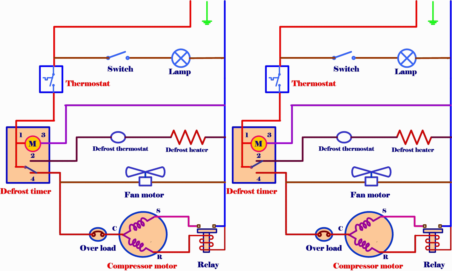
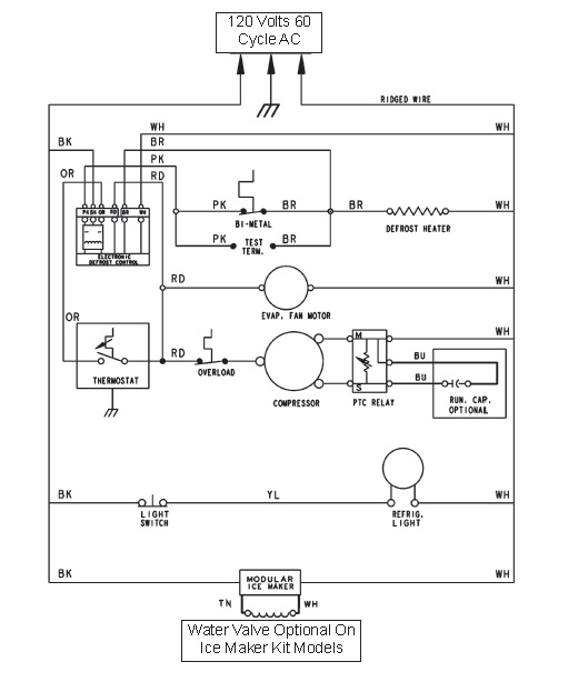
In this video you can learn about the defrost timer wiring diagram of a frost free refrigerator and circuit diagram step by step details. Paragon defrost timer 8145 20 wiring diagram paragonwire bunch ideas throughout 11 paragon defrost timer 8145 20 wiring diagram with 10 diagram these electro mechanical controls are used on many different types of commercial refrigeration equipment including walk in boxes. 800 defrost timer wiring diagram products are offered for sale by. You can test the defrost timer for continuity.
They were quite helpful in figuring out a. Essentially, this means that at regular intervals the timer switches its focus between cut all power to your refrigerator and begin removing the timer by unscrewing any screws and carefully removing any connected wires. A walk in having ice ups gets a defrost timer installed. It may be a problem with your thermostat or defrost timer.
Defrost timers can be adjusted to initiate defrost from just once a day to several times a day. 945 x 1242 jpeg 170 кб. Walk in freezer defrost timer wiring diagram | free wiring. While servicing this display cooler for an unrelated problem, i noticed the defrost timer installed in a way that will almost the diagram below shows first how it is currently connected and then how we rectified the situation.
If none of the terminals are labeled, you can locate the common terminal by determining which terminal coincides with the white wire in the connector plug. The only timer ive seen on a walk in cooler was factory installed with the cooling equipment. Defrost timers are used to shut off the refrigerator compressor and the evaporator fan motors. March 25, 2019 bryan orr no comments.
It is usually included in the appliance's wiring diagram which is most often located. The defrost timer eventually switches into defrost mode and supplies power to the defrost heater(s) to melt any frost that has accumulated on the evaporator for these, check the appliance's 'tech sheet' for instructions. A mechanical defrost timer controls the defrost cycle of the freezer. I agree in theory you should not need a defrost timer.
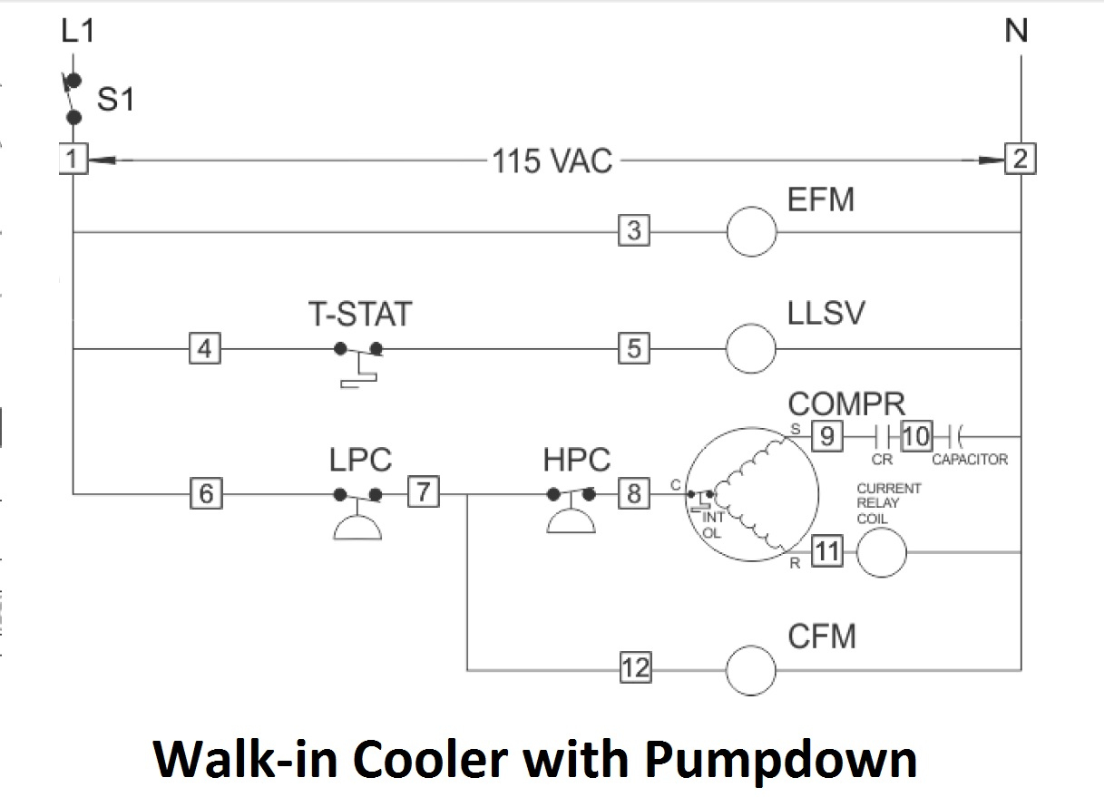
Heatcraft walk in cooler wiring diagram download. Refrigerator won't cool troubleshooting video: Alibaba.com offers 800 defrost timer wiring diagram products. Your refrigerator defrost timer's job is to switch between fan mode and defrost mode.
