Vehicle Speed Sensor Wiring Diagram
The three pins connected to the connectors came out.
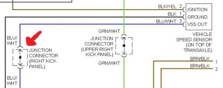
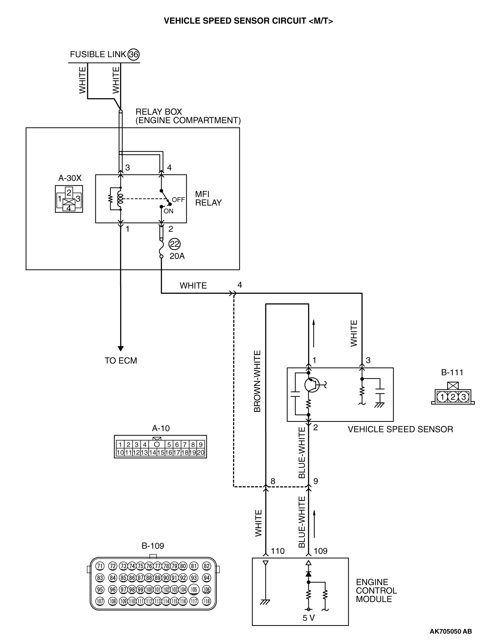
Vehicle speed sensor wiring diagram. I have an orange, purple and white with orange stripe coming off the sensor. Fuse panel layout diagram parts: A vehicle speed sensor's job is relatively simple. The ecm receives two vehicle speed sensor signals via can communication line.
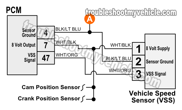
Next, connect the red multimeter lead to the battery positive terminal and the black lead to the. Start by consulting the wiring diagram for your vehicle to determine which pin on the connector is which. Wheel speed sensor operation & testing. The speed sensor indeed has three wires going to it.
Here's a brief description of the throttle position sensor (tps). This diagnostic trouble code (dtc) is a generic powertrain code, which means i like to start my diagnosis with a visual inspection of system wiring, speed sensors, and connectors. Please be sure to read the instruction manual for the the rev speed meter requires both the instruction manual and the wiring diagram for proper even though a vehicle is listed in this manual. + test signal input/output (mation.
- Chinese Atv Starter Solenoid Wiring Diagram
- 2012 Ford Focus Wiring Diagram Pdf
- 2008 Ram Wiring Diagram
The ecm uses these signals for ascd control. The wheel speed sensor is the essential component that the pcm uses to calculate vehicle speed. It is used by factory systems, e.g., speedometer or the system supporting the steering wheel (e.g., electrical support system). 1998 suzuki sidekick front engine fuse box diagram.
Chrysler wiring diagrams are designed to provide information regarding the vehicles wiring content. Digital wave is produced as tone wheel rotate according as hall sensor principle. I want a wiring diagram for isuzu fvz. Pressure sensor & wiring diagram.
The 3 wire speed sensor is externally powered, so you will need a power source of some form. The 3 wire speed sensor output signal is a square wave signal that connects between the input the speed sensor outputs 4 pulses (high to low voltage transitions) for each speed sensor revolution. .honda accord speed sensor plug wiring diagram speed sensor plug wiring diagram i need 1996 honda accord 2dr 2,2 liter vtech diagram is courtesy of honda. 0 km/h (0 mph) 60˚c (176˚f) or more (d) accelerator pedal opening angle :
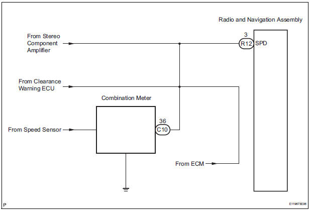
One is sent from combination meter, and the other is from tcm (transmission control module). Throttle position sensor (tps) wiring diagram (part 1). I would like use the native wheel after some readings about wss i saw a technology of sensor which gives current square signal whose the. The vss generates a signal that increases in frequency vss types include:
I would repair open or shorted circuits as required and clean. Map_sensor_wire_diagram%202 isuzu ftr wiring diagram.jpg. There are a number of different arrangements which are used to connect the vehicle speed sensor. A block diagram of the digital system (including the instrumentation computer) that determines vehicle speed from the speed sensor is depicted in fig.
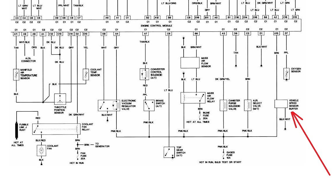
The vehicle speed sensor 2 is not i n function. The output speed sensor is located on the transmission as indicated in the diagram i have put up. The vehicle speed (vss) sensor input is used by the pcm to determine vehicle speed. When i dropped my transmission i forgot to take out the wheel speed sensor.
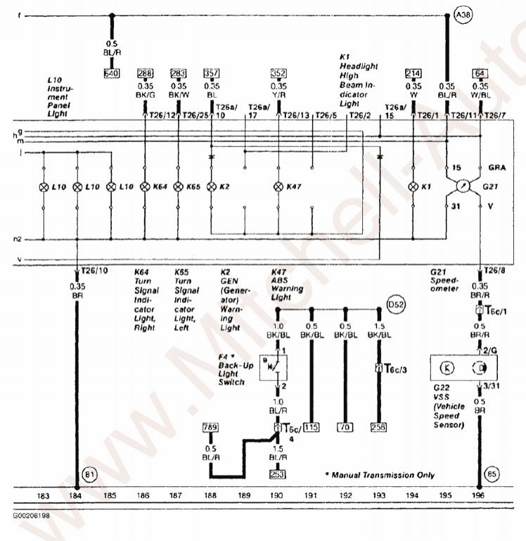
Back up lamp switch, battery, starter motor, front adjustable shock absorber, oil pressure switch, body ground, neutral position switch, transfer switch, vehicle speed sensor. Iagnose, calibrate and program equipment via k tine: As you can probably guess, the vehicle speed sensor (vss) is used to determine vehicle speed. Right now my speedometer isn't working and i hope that it's the wiring for the speed sensor.
> wiring diagram for vehicle wss/abs sensor. Typically, ntc sensors are used on vehicles for temperature sensing. Does anyone have the wiring diagram for a 2003 np231j transfer case speed sensor? Related searches for vehicle speed sensor wiring diagram sensor wiring diagramvehicle wiring diagramslight sensor wiring diagramphoto sensor wiring diagrammotion sensor wiring diagramelectric vehicle wiring diagramfree wiring diagrams for vehiclesvehicle wiring diagrams pdf.
Vehicle speed sensor a intermittent. Vehicle's speed sensor is usually placed in the gearbox. Download data via rs 232 interface; All conditions below are detected continuously for 8 sec.
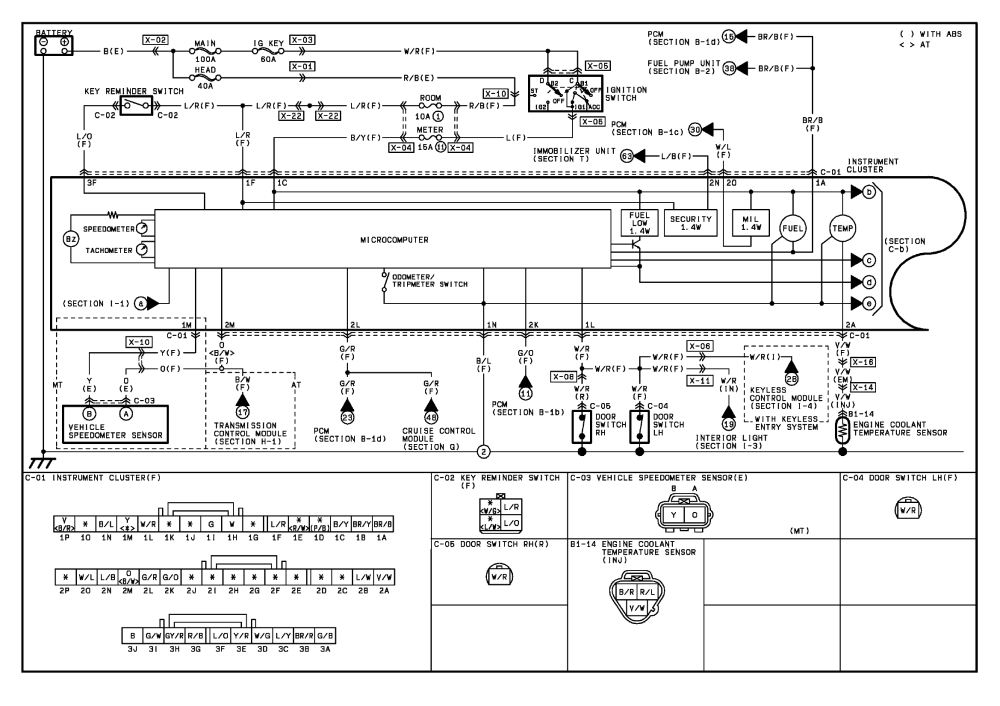
Note that the external wiring diagram in this sensors and wiring section is entirely separate from, though similar to, the relay board. The relay board takes 12v from the vehicle and passes it to the megasquirt® efi controller, but it also handles fuel pump relay and other wiring needed from the. A speed sensor is usually mounted on the side of a wheel axle or of a traction motor axle and driven through a pin screwed into the axle. On my truck, one is black/orange and comes from the gauge fuse, so i'm presuming that it is close perusal of my fsm (the section of the wiring diagram labled combination meter) along with the speed sensor wiring yielded the following info
The vehicle speed sensor (vss) measures transmission/transaxle output or wheel speed. It measures the speed of a rotating shaft and sends that information to the engine management system it's very important to know which type of sensor we are dealing with as the wiring techniques will vary depending on the sensor. Cocr marae te ec wiring diagram tachograph pinout 'the connector onthe front end is used to:
