Universal Speedometer Wiring Diagram
Proper wiring of the speedometer with:
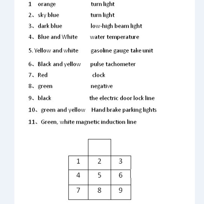
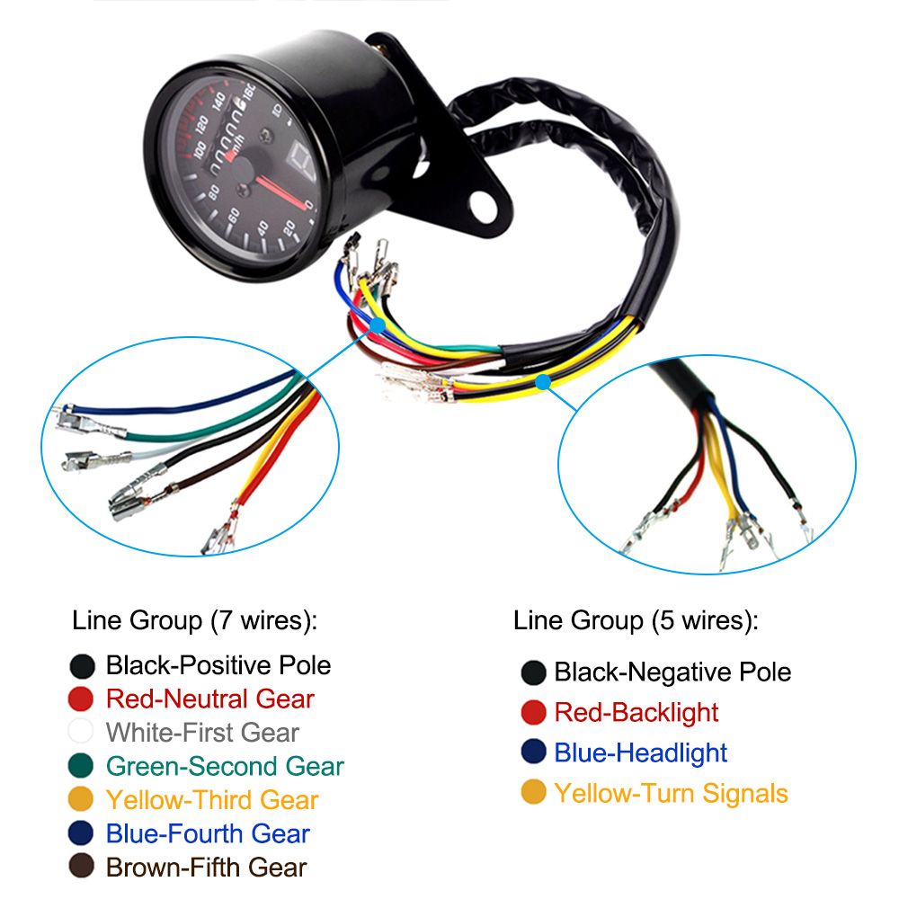
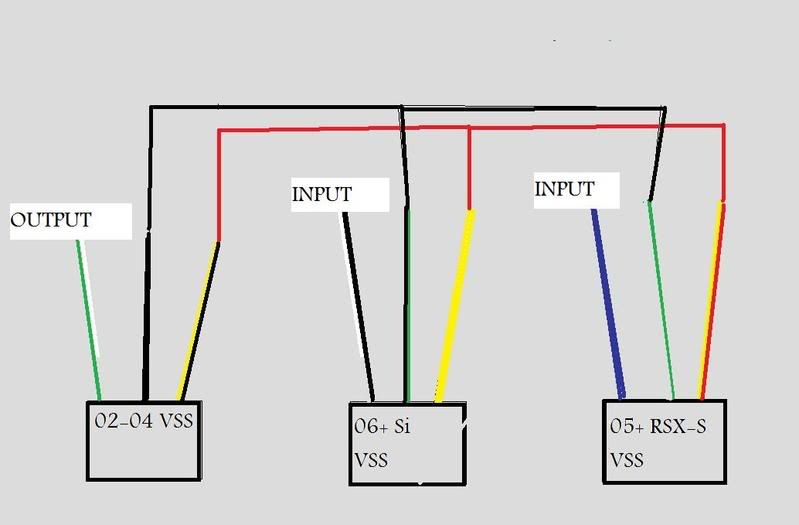
Universal speedometer wiring diagram. Speedometer output function is used to operate an electronic speedometer. The speedometer can be connected to one of the outputs for stepper motor or free injector / aux. This is the method i used for wiring a samdo universal motorcycle replacement speedometer. For a free wiring diagram please visit the website below.
Pulling it stops the speedometer, and lights up a plethora of warning lights. Wiring diagram of 1966 vw speedometer? In all the calculation it has been assumed that the speedometer cabel. In this motor wiring diagram we can see the key components and the wiring of an universal motor i found your diagram confusing because you refer to numbered wires which are not numbered.
Garelli wiring is functionally the same as universal wiring harness brake light wires can be norm open in parallel or normally closed in series. Here is a diagram, again the highlighted area is where you'll be connecting your wire to. This speedometer can measure up to 99 kmph with a resolution of 1 kmph. It also may cause a trouble code to be stored, requiring a dealer visit or that fancy scanner someone should let.
- Ford F350 Rear Axle Diagram
- Murray Mower Drive Belt Diagram
- Pioneer Avh X2600bt Wiring Harness Diagram
Make and model of abs ecu. (this wiring diagram is for those creating their own harness for a v2.2 main board. And sets of the seat belt buzzer every minute forever. I know this speedo can be a pain to install with the lack of instructions/wiring diagram.
Pin 12 carries the speedometer signal (on the can bus!). This gps speedometer sending unit is the latest in technology and will simplify your speedometer installation. The odometer on this speedometer will read from 1 to. The range can be increased up to 999 kmph by adding another the same speedometer can be used other vehicles by making similar calcualtions.
I could guess what you mean but i do not think it wise to guess where a dangerous voltage/current is used. Speedhut speedometers are universal and can be adapted to almost any automotive application. On the basis of vehicle speed, it generates a square wave signal with a frequency proportional to the vehicle speed. Circuit diagram for this analog speedometer is simple, here we have used 16x2 lcd to show speed in digital form and stepper motor to rotate rest of connections are given in circuit diagram.
Wiring diagram ( pin out ) speedometer vario 125/150. The 1998 vw cruise control wiring diagram can be obtained from most vw dealerships. Navistar / international wiring diagrams. .speedometer wiring dia motorcycle wiring diagramsmotorcycle wiring diagrams for freeyamaha motorcycle wiring diagramsfree honda motorcycle wiring diagramshonda motorcycle wiring diagrams pdfmotorcycle wiring schematicssimple motorcycle wiring diagrambig dog motorcycle wiring diagram.
Redesigned smaller version with improved function set. Wire color where to blk = black ground speedometer tachometer tan/wht = tan/white oil light tan/blk = tan/black temperature light tan = tan temperature gauge temperature/oil wiring diagrams. See speedo senders below for available auto the speedometer should be calibrated to ensure accurate operation after installation. Universal wiring actual this is for sale in.
You can use 1n4004/3/2 for diodes if they are more available. Installing the iztoss universal speedometer on my honda cb750. Iztoss/welugnal universal speedometer set up and calibration | cafe racer rebuild. The latest in electronic speedometer senders.
To locate the correct wiring diagram for your vehicle you will need: 31 reviews | 27 answered questions. Be sure you have the diode orientation as shown in the diagram. Wiring diagram speedometer speedometer wiring shorting wat colour wire is for the rev counter at the back of instrument cluster on a vw caddy.hi anonymous, check the wiring and connections from speedometer to the speed sensor.
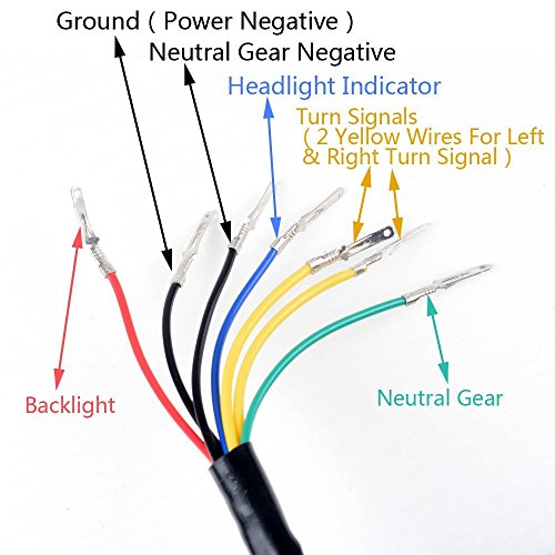
The 2007 model wiring diagram shows pin#3 as the tach output from the speedometer, but that is not shown on later diagrams. Note:it dose't come with a wire diagram,you can easily install follow the instruction above,any quetion plz contact us. Speedometer or tachometer signal converters for engine conversions. Electrical and technical automotif blog.
You must use a main relay' that supplies both the injectors and your megasquirt® controller, as shown in the external wiring diagram above. I also go over the wiring diagram and point out a few issues.








:sharpen(1,0,false):quality(100)/product/38/308601/6.jpg)