Triangular Load Shear Force Diagram
4 Internal Forces In Beams And Frames Engineering Libretexts

Lecture 23 And 24

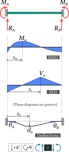
2 A Beam With A Uniform Flexural Rigidity Ei Is Loaded By
You are trying to construct the moment diagram by jumping in the middle of the process without completing the basic steps (1 and 2 above) first.
Triangular load shear force diagram. This article will discuss the steps for drawing. Shear forces occurs when two parallel forces act out of alignment with each other. Shearing force diagrams resulting from the action of concentrated loads on a horizontal beams consist of horizontal straights lines with the vertical jumps at tat load. Shear force and bending moment diagrams.
A simply supported beam subject to a uniformly distributed load (udl). As shown in the diagram coupled load is that in which two equal and opposite forces acts on the same span. Axial, shear and bending diagrams 27: Triangular load is that whose magnitude is zero at one end of span and increases constantly till the 2nd end of the span.
Shear force diagram bending moment diagram effect of couple reactions ra + rb = 20 x 4 = 80 ma, rb x 10 = 40 + 20 x 4 x 14. As we need to convert the udl in to load, we multiply the length of the cantilever beam with udl acting upon. Drawing shear force and bending moment > how to find a shear force diagram (sfd) of a simple beam in this tutorial, we will look at calculating the shear force diagram of a simple beam. So we know on this, on this beam, all of these applied external forces and moments.
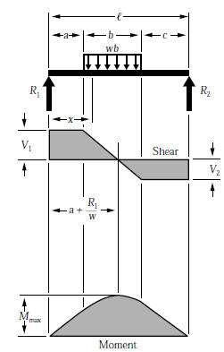
Define and calculate shear force in a beam, draw and calculate bending moment in a beam. Shear force diagram, shear force equation and bending diagram are very important from design point of view. The shear force diagram crosses the base line at a distance x from the end of the beam, given by in constructing the shear force diagram we can make use of the facts that, as established above, the shear force is constant over unloaded bays of the beam, varies linearly when the loading is uniformly. Introduction to axial & shear forces and bending moments 26:
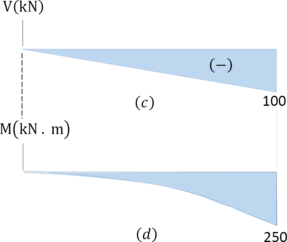
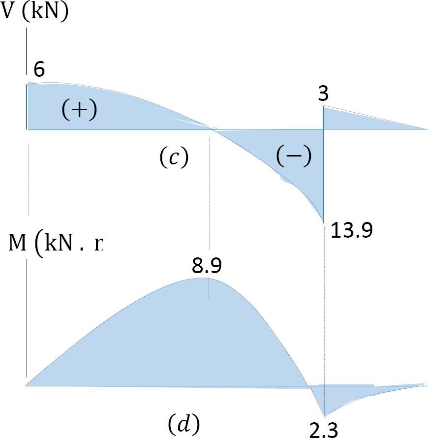
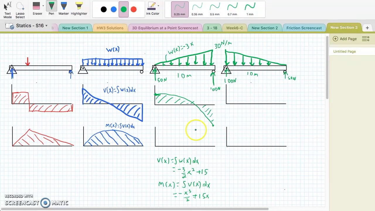
This video shows how to solve beam with triangular load. From the above equations we can sketch the shearing force and bending moment diagrams. The way you go about this is. I'm trying to calculate the shear force diagram in terms of $x$, but i'm unsure about the intensity $w(x)$ of the triangular load distribution between $0m after reading multiple textbooks and watching several videos, i finally found out that if the maximum load of a triangular load distribution is at the.
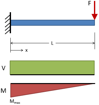
Draw the shear force (sf) and bending moment (bm) diagrams. Since the segment is chosen at a point x where there is no concentrated forces or moments, the result of this analysis will not apply to points of concentrated the slope of the shear diagram at a point is equal to the intensity of the distributed loading w(x) at that point. For example, in a large boiler made from sections of sheet metal plate riveted together a cantilever of length l carries a concentrated load w at its free end. As the shear force is 10n all along the beam, the plot is just a what if there is more than one force, as shown in the diagram below, what would the shear force diagram look like then?
Uniformly varying load w n/m w n/m 1/3 l l 2/3 l load act the centroid of the triangular area there will be parabola in both s.f. Shear force diagram bending moment diagram figure 9.23. Internal shear force (v) ≡ equal in magnitude but opposite in direction to the algebraic sum (resultant) of the components in the direction perpendicular to the axis of the beam of all external loads and support reactions axial force, shear force and bending moment. In this video triangular load has been calculated, shear force diagram and bending moment diagram.
Bendingmomentdiagram.com is a free online calculator that generates bending moment diagrams (bmd) and shear force diagrams (sfd) for most simple it will work for all simply supported, determinant beams and is capable of taking point loads, concentrated moments and distributed loads. The distributed loads can be arranged so that they are uniformly distributed loads (udl), triangular distributed loads or trapezoidal distributed loads. The lines of action of both the forces are parallel to each other but. A shearing force diagram is a graph showing the variation of the shearing force along the length of a beam or other structural member.
Shear force and bending moment diagrams. And i found the area under the load curve, it's just a triangular area. When we can be constructing the shear force diagram than use the point that the shear force, is constant over the unloaded bays of the. Shear force diagram is the most important first step toward design calculations of structural or machine elements.
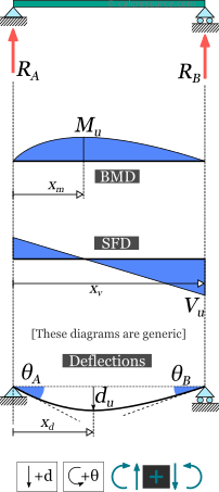
For maximum shear force to obtain we ought to multiply load and distance and it surely occurs at the. The supporting columns are of equal height and are fixed at the base. And come up with the shear force diagram. In this example, the structure and the loading are symmetrical.
Problem 846 sketch the shear diagram for the continuous beam shown in fig. Draw the shear force diagram and bending moment diagram for the beam. Shear and bending moment diagrams are analytical tools used in conjunction with structural analysis to help perform structural design by determining the value of shear force and bending moment at a given point of a structural element such as a beam. A shear force diagram for a structural member.
The shear force between point a and b is usually plotted on a shear force diagram. (the sign is taken to be positive because the resultant force is in downward direction on right hand side of the section). Using the shear force diagram, construct the bending moment diagram. Relations between distributed loads and internal shear forces and bending moments.
Calculate the deflection of steel, wood and other materials. A force is acting at the top of a building frame as shown. Cantilever beam calculation carrying a triangular and a concentrated load. A shearing force occurs when a perpendicular force is applied.
Gallery of Triangular Load Shear Force Diagram
Beam Deflection Tables Mechanicalc
Moment Diagram With Triangular Load Physics Forums
De 12 Lesson 19 Solved Examples Based On Shear Force And
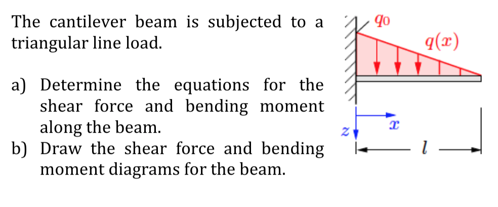
Solved The Cantilever Beam Is Subjected To A A Triangular
Simply Supported Beam Calculator Calcresource
Beam Formulas With Shear And Mom
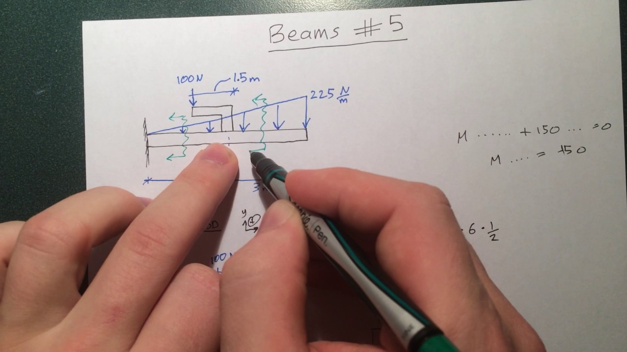
Beams 5 Bending Moment And Shear Force Diagrams Example 3 Arm Extension Triangular Loading
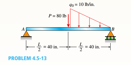
The Simple Beam Ab Supports A Triangular Load Of Maximum

Shear And Moment Diagram Example 2 Mechanics Of Materials And Statics
How To Calculate The Zero Shear Point From A Parabolic Shear
1 4 Internal Forces In Beams And Frames Engineering Libretexts
Fixed Beam Calculator Calcresource

100 Best Hibbeler Engineering Statics 14th Editin Pdf Images
Shear And Moment Diagrams For Combined Loadings
What Is The Bending Moment Diagram Of A Cantilever Subjected
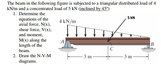
Solved Determine The Equations Of The Axial Force Shear

Sfd Amp Bmd Shear Force Amp Bending Moment Diagram
