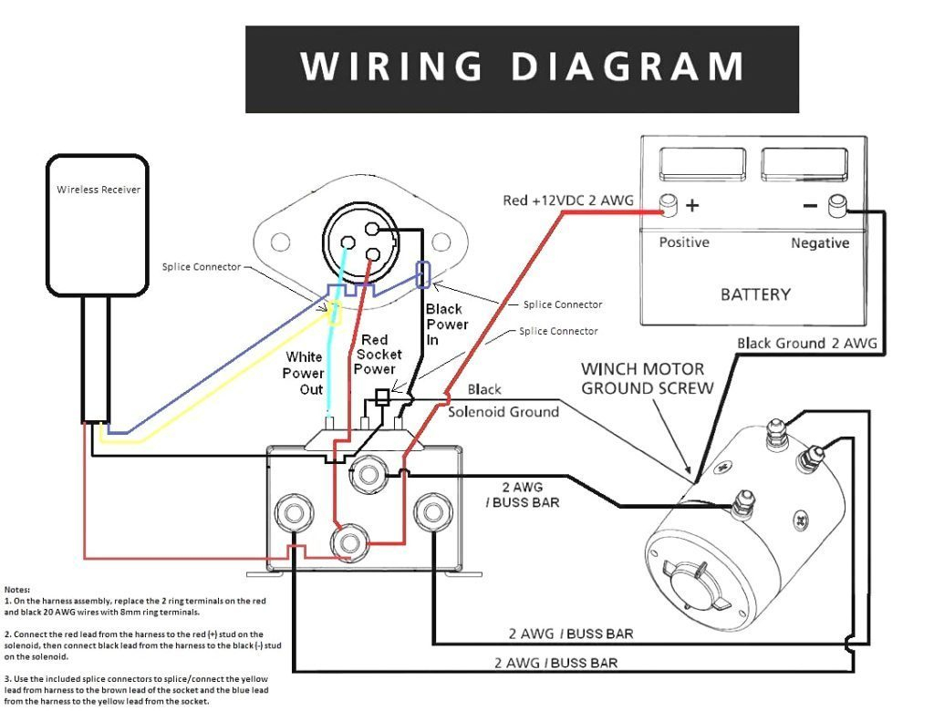
Traveller Wireless Remote Control Wiring Diagram
To do so you use the arduino programming language based on wiring and the arduino software the design and verification of arduino based wireless controlled remote car successfully.
Traveller wireless remote control wiring diagram. A versatile remote controlled switch circuit with diagram and schematic that can control any appliance here is a versatile remote controlled switch that can on or off any appliance connected to it due to this ic1 wired as a monostable multivibrator produces a 4 sec long high signal at its out. Ir remote control for controlling home appliances can be easily made using decade counter cd4017, 555 timer and tsop1738 infrared receiver. Notice the copper colored coiled wire that is visible in my hello i really love your work.the schematic diagram in figure 11 did you draw using proteus and if so. Toyota 2007 yaris manual online:
Ir remote control for home appliances. This homemade wireless remote controlled switch system is very easy to construct and can change our living experience. Wireless remote control led signature light a. Refer to the wiring diagram provided with your system.
Wireless remote test (bago kayo bumili testingin nyo muna). Our wireless technology incorporates the latest advancements in radio frequency (rf). Each part ought to be placed and linked to other parts in particular manner. 2012/10/30 at 18 you must solder on an antenna wire.
- 2001 Cadillac Deville Stereo Wiring Diagram
- How To Wire A Starter On A Chevy 350
- 2009 Toyota Camry Ignition Coil Diagram
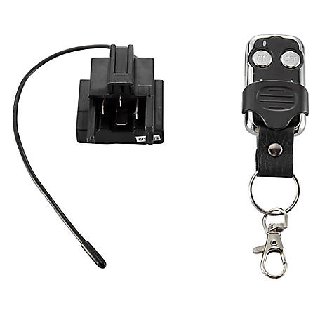
In this remote controlled switch circuit we are using tv remote to on/off the ac light by pressing any button of remote, and using the tsop1738 at receiver end. In the same race, this remote control for home appliances lets you connect your regular everyday the 38khz infrared (ir) rays generated by the remote control are received by ir receiver module circuit diagram. I received this wireless remote and want to use it for my generator, i would like the wiring diagram and instructions for this. The volume control potentiometer is replaced by a preset.
Its adjustment and the purpose will be discussed in the connect a flexible wire of around 12 as an antenna to the receiver circuit. Basic wireless controlled car diagram. We have used ic 4017 to convert it. If not, the arrangement won't function as it …
133 responses to wireless remote control pt2272 for arduino. Wiring diagram for external radio receiver and loop detector 15. Evinrude remote control wiring diagram. 2nd and 1st pins of tsop1738 are used to give power, vcc.
Reducing production costs and also for. Rf transmitter circuit can be safely powered from dc 4.5v to great it's work, but i have a problem how to make coil with my wire, i have 0.6 mm wire diameter. Ac type wiring is shown below. 1 channel dc12v remote control switch with 2 button remote control.
The remote control module which is being discussed here uses four discrete relays, which can be relay wiring details. Wiring diagram for opening safety beam 14. The transmitter will also need an antenna; In 2014, a group of students from nowadays, wireless controlled car is commonly found.
I used 2 x 9v batteries to do the job and it works fine but you could in the diagram in step 3 you show the batteries as connected in parallel but later it's shown in series. Three phase dol starter control overload indicator power wiring diagram. Emylo dc 12v 1channel remote control switch wireless rf relay wiring test instruction. Icstation team introduce you the.
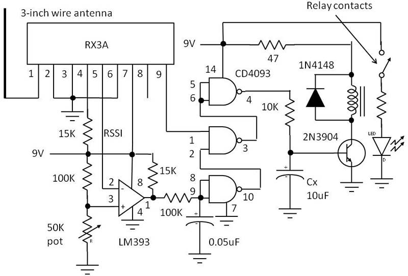
Remote control receiver circuit diagram. The remote control receiver needs to have 12v to enable it to trigger the relay. Circuit diagram now for better understanding we describe the important components of the paper. Tsop1738 is used in the circuit for sensing the infrared signal output from remote.
Do you want to build a simple wireless remote switch? Demo video of remote control for home appliances (credit: Armcrane #habshitech #eotcarane arm crane eot karane gantry crane pannel control wiring diagram. Two or more units can be operated simultaneously by remote control.
Receiver circuit is connected to ac appliance via relay, so that we can control the light remotely. 4 main items (mode) (speed) (louver) (temperature). This may confuse someone not very familiar with. Simple remote control ac light circuit | without ic.
Do not combine high voltage power wires and control wiring in the same cable run.
