Tractor Alternator Wiring Diagram
Come join the discussion about specifications, modifications, troubleshooting, maintenance, and more!
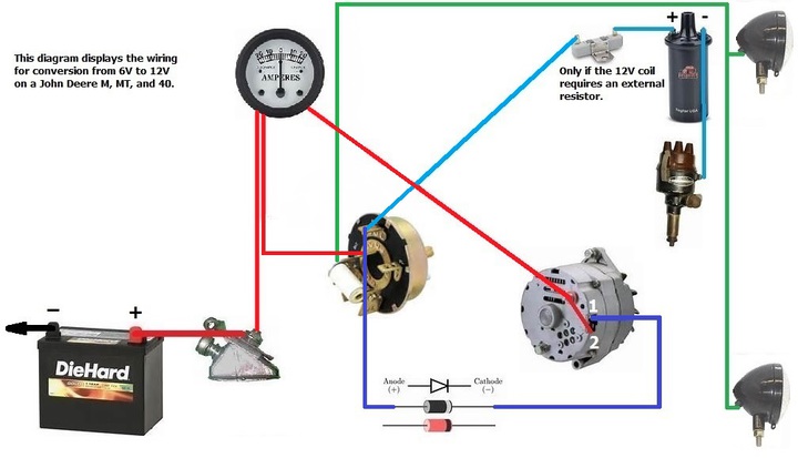
Tractor alternator wiring diagram. See the wiring diagram above (rough schematic of engine wiring) for the alternator with an internal voltage regulator. We are showing this example on an mf 35 deluxe tractor but the same wiring will work on all single wire alternators. The diagrams above show how to wire the system, starting with the 12v generator made with the automotive alternator, going to the battery bank to keep it charged. I checked the box for a wiring diagram and found none, just a test report on the alternator.
Identify the system being tested by the wire or wires that extend from behind the flywheel. Perkins 100 series manual online: You will need to change your starter to a 12 volt.wiring diagram for connecting a new alternator to a john deere power tech 4.5 liter engine wiring diagram jd power tech 4.5l from alternator,put. A forum community dedicated to all tractor owners and enthusiasts.
An alternator is made up of two main parts: Wiring diagram how an alternator works. Sir, can you show wiring diagram with wires from modified motor to esc speed controller? Circuit cable number alternator charging starter motor solenoid std glow plugs (via glow signal) wiring diagram maximum circuit resistance the resistance of battery.
- Kenwood 16 Pin Wiring Harness Diagram
- 2011 Transit Connect Fuse Box Diagram
- Gm Factory Radio Wiring Diagram
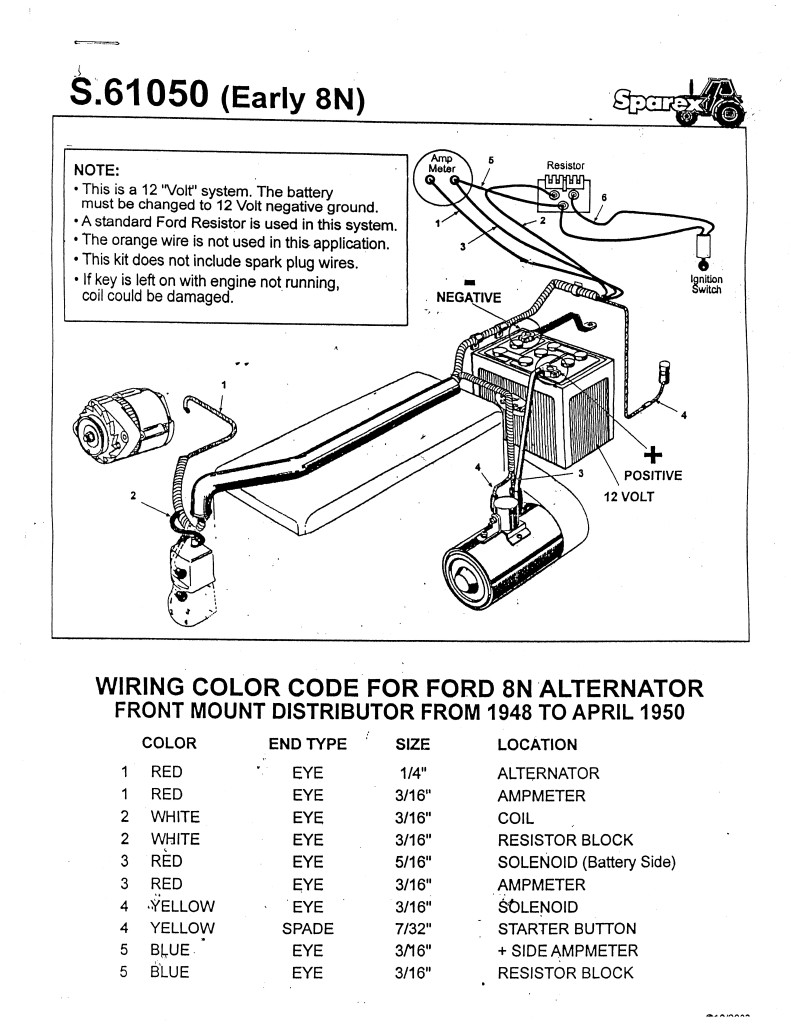
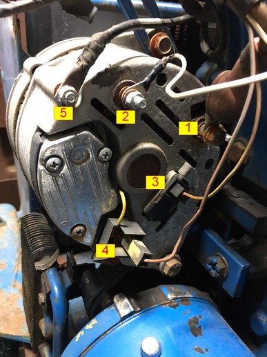
Downloads factory manual detailing briggs engine wiring/alternators. I have purchased the new alternator plugs, but i need a wiring diagram for the ford alternators with two plugs. The engine is kaput, but it still has lots of good parts. Ford 6610 wiring diagram tractor alternator a light on enthusiasts.
The more bells and whistles on a tractor, the more wires and switches. I need a wiring diagram for the voltage regulator alternator. Jump to navigation jump to search. We are showing this example on an mf 35 deluxe tractor but the same wiring will work.
There is no wiring diagram for the built in alternator as it has no adjustment, it is preset. Electromechanical device that converts mechanical energy to electrical energy diagram of a simple alternator with a rotating magnetic core (rotor) and stationary wire (stator) also showing the current. 800 x 600 px, source: Any wiring diagram with the new alternator?
Be professional with your tractor's wiring! This is your basic tractor wiring diagram. This video shows you how to wire a single wire alternator on tractors. 1976 ford alternator wiring diagram wiring diagram blog.
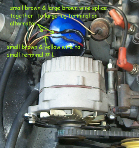
International tractor wiring diagram parts and brilliant ford 2000, size: The wiring is shot, scabbed together from previous owner. A rotor and a stator. I made a note of each color wire was attached to the alternator before removing it, and also found a wiring diagram so i could identify.
This video shows you how to wire a single wire alternator on tractors. Record the number and color of the wires and the color and general type of connector the wires terminate in. Dual alternator battery isolator wiring diagram. When wiring an alternator with an internal voltage regulator, remove the blue and green wires from the old external regulator under the back seat and splice them together.
Guide to briggs electrical systems with wiring diagrams. The rotor rotates in the stator, and the field poles get projected onto the rotor body of the alternator.… rather, the central polar area is provided with slots for housing the field windings as we can see from the diagram above. 12v alternator wiring diagram 1 wiring diagram source. Bobber electrical circuit diagram electrical projects chevy ford tractors voltage regulator us cars mechanical engineering.
Here are a few of the top drawings we obtain from various resources, we hope these photos will work to you, and also hopefully really relevant to exactly what you want regarding the. To view wiring diagrams and misc. Wiring_diagram_te20_to20_to30.pdf, fds277.pdf, specialty/wiring_diagram_te20_to20_to30.pdf, i & t shop service manual, ihs891.pdf, ihs483.pdf, restoration quality wiring harness for tractors using. These cards supply information on the different alternator systems provided by briggs & stratton.
Because the ignition can get fed by the alt thru gahi's diagram is the correct way to wire a gm 10si/12si, and utilize all the benefits of that great design. When connecting the wires for an electrical system, don't just make a connection by twisting bare wires together by hand and taping them up. Mtz kirovets k744 wiring diagram (10.3 mb). The above diagram will give you an at a glance idea of how a tractor is wired up.
I have an old alternator off a 1981 civic wagon. Alternator circuit diagram ( battery charging system) ,components of alternator.in hindi. Some better esc have switch for changing direction, but you can do manually switching two phase. Tractor must be converted to negative earth system alternator regulator charge light.
This battery bank in turn supplies the needed 12v input for the 110v inverter(s) which can. There are entirely too many different setups to even begin drawing or posting all of them on this website. Basic wiring diagram for all garden tractors using a here is a basic wiring diagram that applies to all vintage and antique lawn and garden tractors using a wire harness, tractor parts, harness repair, alternator we build taped or braided wire harnesses and tractor parts to fit farm tractors. One of the easiest and best improvements that can be made to an older tractor is to replace the original generator with an alternator.
First of all, an engine's ignition system is completely separate from its electrical system. This is usually through the case but some units require a separate connection usually for the solid state regulator inside the case. I need to figure out how the charging and starting circuits are wired.any help would be very much.


